Lexus RX (RX 350L, RX450h) 2016-2026 Repair Manual: Terminals Of Ecu
TERMINALS OF ECU
CHECK MAIN BODY ECU (MULTIPLEX NETWORK BODY ECU) AND INSTRUMENT PANEL JUNCTION BLOCK ASSEMBLY
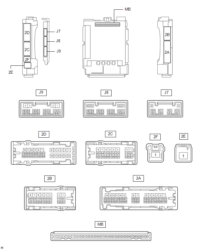
(a) Remove the main body ECU (multiplex network body ECU) from the instrument panel junction block assembly.
Click here .gif)
(b) Reconnect the instrument panel junction block assembly connectors.
(c) Measure the resistance and voltage according to the value(s) in the table below.
HINT:
Measure the values on the wire harness side with the connector disconnected.
| Terminal No. (Symbol) | Wiring Color | Terminal Description | Condition | Specified Condition |
|---|---|---|---|---|
| MB-31 (BECU) - Body ground | - | Battery power supply | Always | 11 to 14 V |
| MB-32 (IG) - Body ground | - | Ignition power supply (IG signal) | Engine switch on (IG) → off | 11 to 14 V → Below 1 V |
| MB-30 (ACC) - Body ground | - | Ignition power supply (ACC signal) | Engine switch on (ACC) → off | 11 to 14 V → Below 1 V |
| MB-11 (GND1) - Body ground | - | Ground | Always | Below 1 Ω |
| MB-13 (LCTY) - Body ground | - | Rear door courtesy light switch LH input | Rear door LH closed (OFF) | 10 kΩ or higher |
| Rear door LH open (ON) | Below 1 Ω | |||
| MB-2 (RCTY) - Body ground | - | Rear door courtesy light switch RH input | Rear door RH closed (OFF) | 10 kΩ or higher |
| Rear door RH open (ON) | Below 1 Ω |
CHECK COMBINATION METER ASSEMBLY
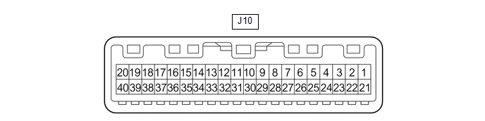
(a) Disconnect the J10 combination meter assembly connector.
(b) Measure the voltage and resistance according to the value(s) in the table below.
HINT:
Measure the values on the wire harness side with the connector disconnected.
w/o Rear No. 2 Seat| Terminal No. (Symbol) | Wiring Color | Terminal Description | Condition | Specified Condition |
|---|---|---|---|---|
| J10-22 (B) - Body ground | G - Body ground | Battery power supply | Always | 11 to 14 V |
| J10-21 (IG+) - Body ground | GR - Body ground | Ignition power supply | Engine switch off | Below 1 V |
| Engine switch on (IG) | 11 to 14 V | |||
| J10-31 (ES) - Body ground | W-B - Body ground | Ground | Always | Below 1 Ω |
| J10-14 (RLSB) - Body ground | R - Body ground | Rear LH seat belt buckle switch signal | Rear LH seat belt fastened | 10 kΩ or higher |
| Rear LH seat belt unfastened | Below 1 Ω | |||
| J10-13 (RCSB) - Body ground | B - Body ground | Rear center seat belt buckle switch signal | Rear center seat belt fastened | 10 kΩ or higher |
| Rear center seat belt unfastened | Below 1 Ω | |||
| J10-12 (RRSB) - Body ground | W - Body ground | Rear RH seat belt buckle switch signal | Rear RH seat belt fastened | 10 kΩ or higher |
| Rear RH seat belt unfastened | Below 1 Ω |
| Terminal No. (Symbol) | Wiring Color | Terminal Description | Condition | Specified Condition |
|---|---|---|---|---|
| J10-22 (B) - Body ground | G - Body ground | Battery power supply | Always | 11 to 14 V |
| J10-21 (IG+) - Body ground | GR - Body ground | Ignition power supply | Engine switch off | Below 1 V |
| Engine switch on (IG) | 11 to 14 V | |||
| J10-31 (ES) - Body ground | W-B - Body ground | Ground | Always | Below 1 Ω |
| J10-14 (RLSB) - Body ground | R - Body ground | Rear No. 1 LH seat belt buckle switch signal | Rear No. 1 LH seat belt fastened | 10 kΩ or higher |
| Rear No. 1 LH seat belt unfastened | Below 1 Ω | |||
| J10-13 (RCSB) - Body ground* | B - Body ground | Rear No. 1 center seat belt buckle switch signal | Rear No. 1 center seat belt fastened | 10 kΩ or higher |
| Rear No. 1 center seat belt unfastened | Below 1 Ω | |||
| J10-12 (RRSB) - Body ground | W - Body ground | Rear No. 1 RH seat belt buckle switch signal | Rear No. 1 RH seat belt fastened | 10 kΩ or higher |
| Rear No. 1 RH seat belt unfastened | Below 1 Ω | |||
| J10-8 (RLBT) - Body ground | R - Body ground | Rear No. 2 LH seat belt buckle switch signal | Rear No. 2 LH seat belt fastened | 10 kΩ or higher |
| Rear No. 2 LH seat belt unfastened | Below 1 Ω | |||
| J10-6 (RRBT) - Body ground | W - Body ground | Rear No. 2 RH seat belt buckle switch signal | Rear No. 2 RH seat belt fastened | 10 kΩ or higher |
| Rear No. 2 RH seat belt unfastened | Below 1 Ω |
- *: for 60/40 Split Seat Type
(c) Reconnect the J10 combination meter assembly connector.
(d) Measure the voltage according to the value(s) in the table below.
w/o Rear No. 2 Seat| Terminal No. (Symbol) | Wiring Color | Terminal Description | Condition | Specified Condition |
|---|---|---|---|---|
| J10-35 (RLMT) - Body ground | Y - Body ground | Rear seat belt warning light (LH) output signal | Engine switch on (IG), rear seat belt warning light (LH) off | 11 to 14 V |
| Engine switch on (IG), rear seat belt warning light (LH) on | Below 1 V | |||
| J10-36 (RCMT) - Body ground | W - Body ground | Rear seat belt warning light (center) output signal | Engine switch on (IG), rear seat belt warning light (center) off | 11 to 14 V |
| Engine switch on (IG), rear seat belt warning light (center) on | Below 1 V | |||
| J10-37 (RRMT) - Body ground | B - Body ground | Rear seat belt warning light (RH) output signal | Engine switch on (IG), rear seat belt warning light (RH) off | 11 to 14 V |
| Engine switch on (IG), rear seat belt warning light (RH) on | Below 1 V |
| Terminal No. (Symbol) | Wiring Color | Terminal Description | Condition | Specified Condition |
|---|---|---|---|---|
| J10-35 (RLMT) - Body ground | Y - Body ground | Rear seat belt warning light (rear No. 1 seat LH) output signal | Engine switch on (IG), rear seat belt warning light (rear No. 1 seat LH) off | 11 to 14 V |
| Engine switch on (IG), rear seat belt warning light (rear No. 1 seat LH) on | Below 1 V | |||
| J10-36 (RCMT) - Body ground* | W - Body ground | Rear seat belt warning light (rear No. 1 seat center) output signal | Engine switch on (IG), rear seat belt warning light (rear No. 1 seat center) off | 11 to 14 V |
| Engine switch on (IG), rear seat belt warning light (rear No. 1 seat center) on | Below 1 V | |||
| J10-37 (RRMT) - Body ground | B - Body ground | Rear seat belt warning light (rear No. 1 seat RH) output signal | Engine switch on (IG), rear seat belt warning light (rear No. 1 seat RH) off | 11 to 14 V |
| Engine switch on (IG), rear seat belt warning light (rear No. 1 seat RH) on | Below 1 V | |||
| J10-32 (L) - Body ground | L - Body ground | Rear seat belt warning light (rear No. 2 seat LH) output signal | Engine switch on (IG), rear seat belt warning light (rear No. 2 seat LH) off | 11 to 14 V |
| Engine switch on (IG), rear seat belt warning light (rear No. 2 seat LH) on | Below 1 V | |||
| J10-33 (SW) - Body ground | R - Body ground | Rear seat belt warning light (rear No. 2 seat RH) output signal | Engine switch on (IG), rear seat belt warning light (rear No. 2 seat RH) off | 11 to 14 V |
| Engine switch on (IG), rear seat belt warning light (rear No. 2 seat RH) on | Below 1 V |
- *: for 60/40 Split Seat Type
CHECK AIRBAG SENSOR ASSEMBLY
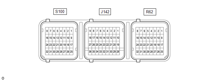
| Terminal No. | Terminal Symbol | Destination |
|---|---|---|
| S100-28 | LBE+ | Front seat inner belt assembly LH |
| S100-27 | LBE- | Front seat inner belt assembly LH |
CHECK OCCUPANT DETECTION ECU

(a) Measure the voltage and check for pulses according to the value(s) in the table below.
| Terminal No. (Symbol) | Wiring Color | Terminal Description | Condition | Specified Condition |
|---|---|---|---|---|
| B-10 (GND) - Body ground | - | Ground | Always | Below 1 V |
| B-6 (IG2) - B-10 (GND) | - | Power source | Engine switch on (IG) | 11 to 14 V |
| B-9 (BGND) - B-10 (GND) | - | Front passenger buckle switch ground | Always | Below 1 V |
| B-7 (BSW) - B-9 (BGND) | - | Front passenger buckle switch signal | Always | Pulse generation |
| b10-1 (SVC1) - b10-5 (SGD1) | R - G | Front occupant classification sensor LH power supply | Engine switch on (IG) | 11 to 14 V |
| b10-2 (SVC3) - b10-6 (SGD3) | GR - W | Rear occupant classification sensor LH power supply | Engine switch on (IG) | 11 to 14 V |
| b10-3 (SIG1) - b10-5 (SGD1) | P - G | Front occupant classification sensor LH signal | Engine switch on (IG) | Pulse generation |
| b10-4 (SIG3) - b10-6 (SGD3) | SB - W | Rear occupant classification sensor LH signal | Engine switch on (IG) | Pulse generation |
| b10-5 (SGD1) - B-10 (GND) | G - - | Front occupant classification sensor LH ground | Always | Below 1 V |
| b10-6 (SGD3) - B-10 (GND) | W - - | Rear occupant classification sensor LH ground | Always | Below 1 V |
 How To Proceed With Troubleshooting
CAUTION / NOTICE / HINT HINT:
Use the following procedure to troubleshoot the seat belt warning system.
*: Use the Techstream.
PROCEDURE 1. VEHICLE BROUGHT TO WORKSHOP
NEXT ...
 Data List / Active Test
DATA LIST / ACTIVE TEST DATA LIST NOTICE: In the following table, the values listed under "Normal Condition" are reference values. Do not depend solely on these reference values when deciding whether ...
Other materials:
Lexus RX (RX 350L, RX450h) 2016-2026 Repair Manual > Instrument Panel Speaker: Removal
REMOVAL CAUTION / NOTICE / HINT for Side:
Use the same procedure for the RH side and LH side.
The following procedure is for the LH side.
PROCEDURE 1. REMOVE NO. 1 INSTRUMENT PANEL SPEAKER PANEL SUB-ASSEMBLY (for Side) Click here 2. REMOVE FRONT NO. 2 SPEAKER ASSEMBLY (for Side) NOTICE: ...
Lexus RX (RX 350L, RX450h) 2016-2026 Repair Manual > Panoramic Moon Roof System: Problem Symptoms Table
PROBLEM SYMPTOMS TABLE HINT:
Use the table below to help determine the cause of problem symptoms. If multiple suspected areas are listed, the potential causes of the symptoms are listed in order of probability in the "Suspected Area" column of the table. Check each symptom by checking the suspect ...
Lexus RX (RX 350L, RX450h) 2016-{YEAR} Owners Manual
- For your information
- Pictorial index
- For safety and security
- Instrument cluster
- Operation of each component
- Driving
- Lexus Display Audio system
- Interior features
- Maintenance and care
- When trouble arises
- Vehicle specifications
- For owners
Lexus RX (RX 350L, RX450h) 2016-{YEAR} Repair Manual

0.0109