Lexus RX (RX 350L, RX450h) 2016-2026 Repair Manual: System Description
SYSTEM DESCRIPTION
FUNCTION OF CONNECTORS
(a) Location of activation prevention mechanism
(b) Function of activation prevention mechanism
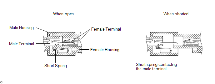
(1) This mechanism is designed to create a short circuit automatically between the positive (+) and negative (-) terminals of a squib power source connector when disconnected.
(2) The short spring contained in the connector creates a closed circuit on the squib side (no potential difference can occur between both terminals), preventing accidental squib deployment when servicing.
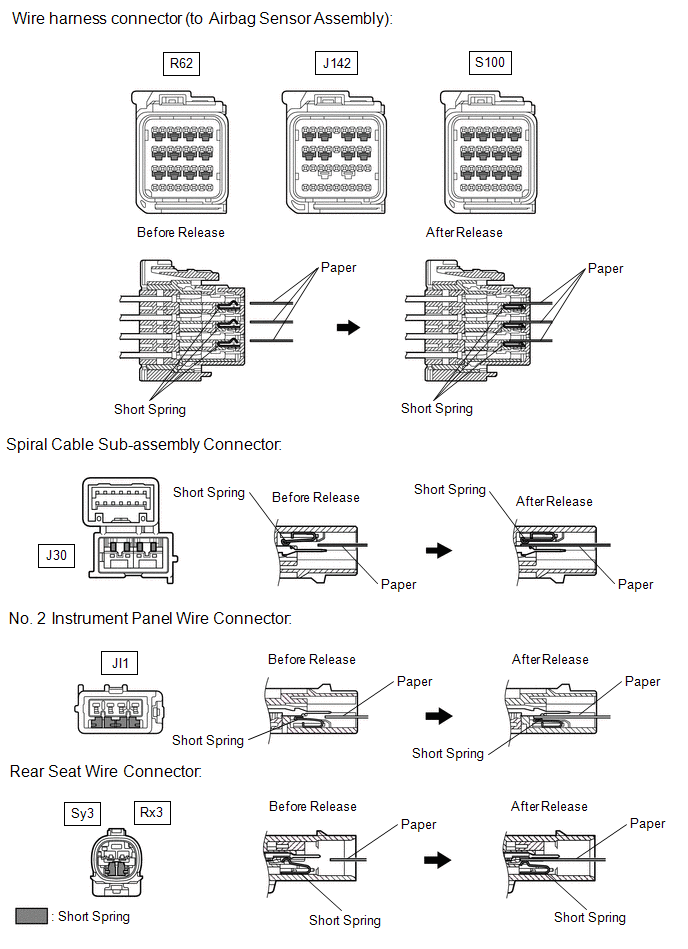
(c) Releasing of activation prevention mechanism
(1) To release the activation prevention mechanism, insert a piece of paper with the same thickness as the male terminal (approximately 0.5 mm (0.0197 in.)) between the terminals and short spring to break the connection.
(2) Refer to the following illustrations concerning connectors utilizing the activation prevention mechanism and its release method.
CAUTION:
Never release the activation prevention mechanism on the squib connector even when inspecting with the squib disconnected.
NOTICE:
- Do not release the activation prevention mechanism unless specified by the troubleshooting procedure.
- To prevent the terminals and short spring from being damaged, always use a piece of paper with the same thickness as the male terminal.
HINT:
To prevent improper operation due to static electricity, etc., the connector of the airbag, pretensioner and selectable force limiter squib circuit has a short mechanism, and the squib terminal is shorted while the connector is disconnected.
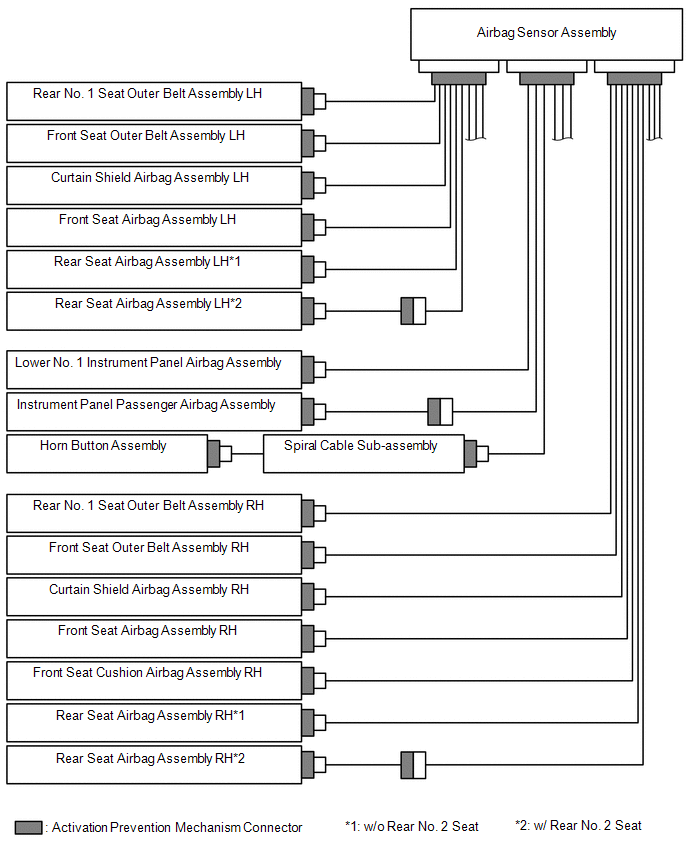
 System Diagram
SYSTEM DIAGRAM Communication Table Transmitting ECU (Transmitter) Receiving ECU Signal Communication Method Airbag Sensor Assembly Occupant Detection ECU
Crash detection signal ...
 How To Proceed With Troubleshooting
CAUTION / NOTICE / HINT HINT:
Use the following procedure to troubleshoot the airbag system.
*: Use the Techstream.
PROCEDURE 1. VEHICLE BROUGHT TO WORKSHOP
NEXT 2 ...
Other materials:
Lexus RX (RX 350L, RX450h) 2016-2026 Repair Manual > Front Evaporator Temperature Sensor: Installation
INSTALLATION PROCEDURE 1. INSTALL NO. 1 COOLER THERMISTOR (a) Install the No. 1 cooler thermistor as shown in the illustration. Installation Position: Part Length A 61.1 mm (2.41 in.) B 50.0 mm (1.97 in.) NOTICE:
Be sure to insert the No. 1 cooler thermistor only once be ...
Lexus RX (RX 350L, RX450h) 2016-2026 Repair Manual > Panoramic View Monitor System: Vehicle Information Unmatched (C168D)
DESCRIPTION This DTC is stored if the parking assist ECU judges as a result of its self check that the vehicle information received via CAN communication and the vehicle information stored in the parking assist ECU do not match. DTC No. Detection Item DTC Detection Condition Trouble Area ...
Lexus RX (RX 350L, RX450h) 2016-{YEAR} Owners Manual
- For your information
- Pictorial index
- For safety and security
- Instrument cluster
- Operation of each component
- Driving
- Lexus Display Audio system
- Interior features
- Maintenance and care
- When trouble arises
- Vehicle specifications
- For owners
Lexus RX (RX 350L, RX450h) 2016-{YEAR} Repair Manual

0.0103