Lexus RX (RX 350L, RX450h) 2016-2026 Repair Manual: Installation
INSTALLATION
PROCEDURE
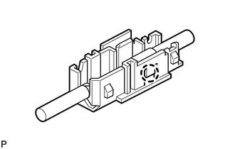
1. INSTALL RADIO SETTING CONDENSER
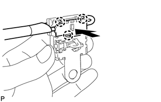
| (a) Engage the claw to install a new terminal cover to the wire harness. NOTICE:
|
|
| (b) Engage the 3 claws to install the new terminal cover with wire harness to a new condenser. NOTICE:
|
|
(c) Engage the clamp to temporarily install a new radio setting condenser with wire harness.
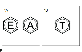
| (d) Install the new radio setting condenser with the bolt. Torque: for Type A : 7.5 N·m {76 kgf·cm, 66 in·lbf} for Type B : 10 N·m {102 kgf·cm, 7 ft·lbf} NOTICE: There are three types of bolts and the tightening torque depends on the type of bolt used as shown in the illustration. Therefore, confirm the tightening torque before installing the bolt. |
|
2. INSTALL DECK TRIM SIDE PANEL ASSEMBLY LH
Click here .gif)
3. INSTALL COOLER (NO. 2 ROOM TEMP. SENSOR) THERMISTOR
Click here
4. INSTALL NO. 2 AIR CONDITIONING CONTROL ASSEMBLY
Click here
5. INSTALL NO. 1 LUGGAGE COMPARTMENT LIGHT ASSEMBLY
Click here
6. INSTALL ROPE HOOK ASSEMBLY
Click here
7. INSTALL NO. 1 LUGGAGE COMPARTMENT TRIM HOOK
Click here
8. INSTALL REAR SEAT SIDE GARNISH LH
Click here
9. INSTALL FRONT DECK SIDE TRIM COVER LH
Click here
10. INSTALL REAR SEAT OUTER TRACK BRACKET COVER LH
for 60/40 Split Seat Type:
Click here
for Captain Seat Type:
Click here
11. INSTALL REAR DOOR INSIDE SCUFF PLATE LH
Click here
12. INSTALL REAR DOOR SCUFF PLATE LH
Click here
13. INSTALL REAR NO. 2 SEAT ASSEMBLY
Click here
 Removal
REMOVAL PROCEDURE 1. REMOVE REAR NO. 2 SEAT ASSEMBLY Click here 2. REMOVE REAR DOOR SCUFF PLATE LH Click here 3. REMOVE REAR DOOR INSIDE SCUFF PLATE LH Click here 4. REMOVE REAR SEAT OUTER TRA ...

Other materials:
Lexus RX (RX 350L, RX450h) 2016-2026 Repair Manual > Safety Connect System: Unable To Connect To Call Center
DESCRIPTION This may occur when the intensity of telephone radio frequency was very weak, or the safety connect system has a malfunction and a DTC is set. PROCEDURE 1. CHECK COMMUNICATION SERVICE CONDITION (a) Move the vehicle. (1) If the vehicle is outside the communication service area, m ...
Lexus RX (RX 350L, RX450h) 2016-2026 Repair Manual > Towing Converter System: Problem Symptoms Table
PROBLEM SYMPTOMS TABLE HINT: Use the table below to help determine the cause of problem symptoms. If multiple suspected areas are listed, the potential causes of the symptoms are listed in order of probability in the "Suspected Area" column of the table. Check each symptom by checking the suspected ...
Lexus RX (RX 350L, RX450h) 2016-{YEAR} Owners Manual
- For your information
- Pictorial index
- For safety and security
- Instrument cluster
- Operation of each component
- Driving
- Lexus Display Audio system
- Interior features
- Maintenance and care
- When trouble arises
- Vehicle specifications
- For owners
Lexus RX (RX 350L, RX450h) 2016-{YEAR} Repair Manual

0.0104