Lexus RX (RX 350L, RX450h) 2016-2026 Repair Manual: Front Airbag Sensor Lost Communication (LH) (B1617,B1618)
DESCRIPTION
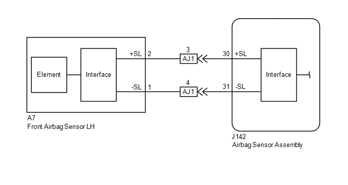
The front airbag sensor LH circuit consists of the airbag sensor assembly and front airbag sensor LH.
The front airbag sensor LH detects impacts to the vehicle and sends signals to the airbag sensor assembly to determine if the airbags, pretensioners and selectable force limiter should be deployed.
These DTCs are stored when a malfunction is detected in the front airbag sensor LH circuit.
| DTC No. | Detection Item | DTC Detection Condition | Trouble Area | Warning Indicate | Test Mode / Check Mode |
|---|---|---|---|---|---|
| B1617 | Front Airbag Sensor Lost Communication (LH) |
|
| Comes on | Does not apply to test/check mode |
| B1618 | Front Airbag Sensor Initialization Error (LH) |
|
| Comes on | Does not apply to test/check mode |
WIRING DIAGRAM
CAUTION / NOTICE / HINT
NOTICE:
After turning the engine switch off, waiting time may be required before disconnecting the cable from the negative (-) battery terminal. Therefore, make sure to read the disconnecting the cable from the negative (-) battery terminal notices before proceeding with work.
Click here .gif)
PROCEDURE
| 1. | CHECK CONNECTION OF CONNECTORS |
(a) Turn the engine switch off.
(b) Disconnect the cable from the negative (-) battery terminal.
CAUTION:
Wait at least 90 seconds after disconnecting the cable from the negative (-) battery terminal to disable the SRS system.
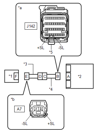
(c) Check that the connectors are properly connected to the airbag sensor assembly and front airbag sensor LH. Also check that the connectors that link the engine room main wire and instrument panel wire are properly connected.
OK:
The connectors are properly connected.
| NG | .gif) | CONNECT CONNECTORS PROPERLY |
|
.gif)
| 2. | CHECK CONNECTORS |
(a) Disconnect the connectors from the airbag sensor assembly and front airbag sensor LH. Also disconnect the connectors that link the engine room main wire and instrument panel wire.
(b) Check that the terminals of the connectors are not deformed or damaged.
OK:
The terminals are not deformed or damaged.
| NG | | REPLACE INSTRUMENT PANEL WIRE OR ENGINE ROOM MAIN WIRE |
|
| 3. | CHECK FRONT AIRBAG SENSOR LH CIRCUIT |
| (a) Connect the connectors that link the engine room main wire and instrument panel wire. |
|
(b) Connect the cable to the negative (-) battery terminal.
(c) Turn the engine switch on (IG).
(d) Measure the voltage according to the value(s) in the table below.
Standard Voltage:
| Tester Connection | Condition | Specified Condition |
|---|---|---|
| A7-2 (+SL) - Body ground | Engine switch on (IG) | Below 1 V |
| A7-1 (-SL) - Body ground | Engine switch on (IG) | Below 1 V |
(e) Turn the engine switch off.
(f) Disconnect the cable from the negative (-) battery terminal.
CAUTION:
Wait at least 90 seconds after disconnecting the cable from the negative (-) battery terminal to disable the SRS system.
(g) Using a service wire, connect terminals 30 (+SL) and 31 (-SL) of connector B.
NOTICE:
Do not forcibly insert the service wire into the terminals of the connector when connecting the wire.
(h) Measure the resistance according to the value(s) in the table below.
Standard Resistance:
| Tester Connection | Condition | Specified Condition |
|---|---|---|
| A7-2 (+SL) - A7-1 (-SL) | Always | Below 1 Ω |
(i) Disconnect the service wire from connector B.
(j) Measure the resistance according to the value(s) in the table below.
Standard Resistance:
| Tester Connection | Condition | Specified Condition |
|---|---|---|
| A7-2 (+SL) - A7-1 (-SL) | Always | 1 MΩ or higher |
| A7-2 (+SL) - Body ground | Always | 1 MΩ or higher |
| A7-1 (-SL) - Body ground | Always | 1 MΩ or higher |
| NG | | GO TO STEP 5 |
|
| 4. | CHECK FRONT AIRBAG SENSOR LH |
| (a) Connect the connector to the airbag sensor assembly. |
|
.png)
(b) Interchange the front airbag sensor LH with RH and connect the connectors.
(c) Connect the cable to the negative (-) battery terminal.
(d) Turn the engine switch on (IG), and wait for at least 60 seconds.
(e) Clear the DTCs stored in memory.
Body Electrical > SRS Airbag > Clear DTCs(f) Turn the engine switch off.
(g) Turn the engine switch on (IG), and wait for at least 60 seconds.
(h) Check for DTCs.
Body Electrical > SRS Airbag > Trouble CodesHINT:
Codes other than DTCs B1612, B1613, B1617 and B1618 may be output at this time, but they are not related to this check.
| Result | Proceed to |
|---|---|
| DTCs B1612, B1613, B1617 and B1618 are not output. | A |
| DTC B1617 or B1618 is output. | B |
| DTC B1612 or B1613 is output. | C |
(i) Turn the engine switch off.
(j) Disconnect the cable from the negative (-) battery terminal.
CAUTION:
Wait at least 90 seconds after disconnecting the cable from the negative (-) battery terminal to disable the SRS system.
(k) Return the front airbag sensor LH and RH to their original positions and connect the connectors.
| A | | USE SIMULATION METHOD TO CHECK |
| B | | REPLACE AIRBAG SENSOR ASSEMBLY |
| C | | REPLACE FRONT AIRBAG SENSOR LH |
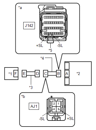
| 5. | CHECK INSTRUMENT PANEL WIRE |
| (a) Disconnect the instrument panel wire connector from the engine room main wire. |
|
(b) Connect the cable to the negative (-) battery terminal.
(c) Turn the engine switch on (IG).
(d) Measure the voltage according to the value(s) in the table below.
Standard Voltage:
| Tester Connection | Condition | Specified Condition |
|---|---|---|
| AJ1-3 (+SL) - Body ground | Engine switch on (IG) | Below 1 V |
| AJ1-4 (-SL) - Body ground | Engine switch on (IG) | Below 1 V |
(e) Turn the engine switch off.
(f) Disconnect the cable from the negative (-) battery terminal.
CAUTION:
Wait at least 90 seconds after disconnecting the cable from the negative (-) battery terminal to disable the SRS system.
(g) Using a service wire, connect terminals 30 (+SL) and 31 (-SL) of connector B.
NOTICE:
Do not forcibly insert the service wire into the terminals of the connector when connecting the wire.
(h) Measure the resistance according to the value(s) in the table below.
Standard Resistance:
| Tester Connection | Condition | Specified Condition |
|---|---|---|
| AJ1-3 (+SL) - AJ1-4 (-SL) | Always | Below 1 Ω |
(i) Disconnect the service wire from connector B.
(j) Measure the resistance according to the value(s) in the table below.
Standard Resistance:
| Tester Connection | Condition | Specified Condition |
|---|---|---|
| AJ1-3 (+SL) - AJ1-4 (-SL) | Always | 1 MΩ or higher |
| AJ1-3 (+SL) - Body ground | Always | 1 MΩ or higher |
| AJ1-4 (-SL) - Body ground | Always | 1 MΩ or higher |
| OK | | REPLACE ENGINE ROOM MAIN WIRE |
| NG | | REPLACE INSTRUMENT PANEL WIRE |
 Front Airbag Sensor (LH) (B1615)
DESCRIPTION The front airbag sensor LH circuit consists of the airbag sensor assembly and front airbag sensor LH. The front airbag sensor LH detects impacts to the vehicle and sends signals to the air ...
 Curtain Shield Airbag Sensor (RH) (B1630,B1632)
DESCRIPTION The side collision sensor RH circuit (bus 1) consists of the airbag sensor assembly, door side airbag sensor RH and rear airbag sensor RH. The door side airbag sensor RH and rear airbag se ...
Other materials:
Lexus RX (RX 350L, RX450h) 2016-2026 Repair Manual > Front Seat Assembly: Installation
INSTALLATION CAUTION / NOTICE / HINT CAUTION:
Be sure to read Precaution thoroughly before servicing.
Click here
Wear protective gloves. Sharp areas on the parts may injure your hands.
HINT:
Use the same procedure for the RH side and LH side.
The following procedure is for the LH sid ...
Lexus RX (RX 350L, RX450h) 2016-2026 Repair Manual > Rear Power Outlet Socket (w/ Rear No. 2 Seat): Removal
REMOVAL PROCEDURE 1. REMOVE REAR NO. 2 SEAT ASSEMBLY Click here 2. REMOVE REAR DOOR SCUFF PLATE LH Click here 3. REMOVE REAR DOOR INSIDE SCUFF PLATE LH Click here 4. REMOVE REAR SEAT OUTER TRACK BRACKET COVER LH for 60/40 Split Seat Type: Click here for Captain Seat Type: Click here 5. ...
Lexus RX (RX 350L, RX450h) 2016-{YEAR} Owners Manual
- For your information
- Pictorial index
- For safety and security
- Instrument cluster
- Operation of each component
- Driving
- Lexus Display Audio system
- Interior features
- Maintenance and care
- When trouble arises
- Vehicle specifications
- For owners
Lexus RX (RX 350L, RX450h) 2016-{YEAR} Repair Manual

0.0106