Lexus RX (RX 350L, RX450h) 2016-2026 Repair Manual: Installation
INSTALLATION
PROCEDURE
1. INSPECT SPIRAL CABLE SUB-ASSEMBLY
NOTICE:
If the steering sensor is installed to a misaligned spiral cable sub-assembly, DTCs for an abnormal steering sensor value such as DTC B1801, C1231 and C1433 will be stored and it will be impossible to correct the problem. If this happens, replace the spiral cable with sensor sub-assembly with a new one.
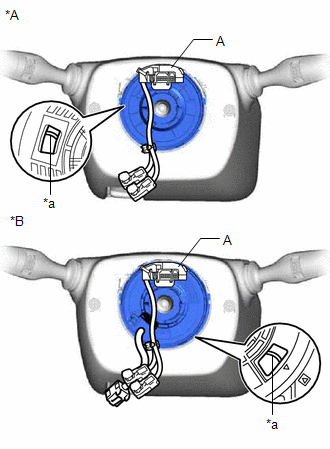
(a) Check if the spiral cable sub-assembly is centered.
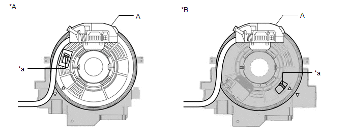
| *A | w/o Heated Steering Wheel System and Pre-collision System | *B | w/ Heated Steering Wheel System or Pre-collision System |
| *a | Flat Cable | - | - |
HINT:
When the spiral cable sub-assembly is centered, the part (A) is positioned at the top and the flat cable shown in the illustration is visible.
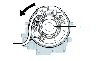
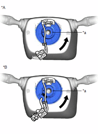
(b) If the spiral cable sub-assembly is not centered, center it.
| (1) While pushing on the interlock shown in the illustration, rotate the spiral cable sub-assembly counterclockwise slowly by hand until it stops. NOTICE:
|
|
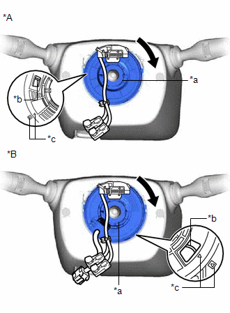
(2) While pushing on the interlock shown in the illustration, rotate the spiral cable sub-assembly clockwise approximately 2.5 times to the position where the alignment marks are aligned and the flat cable shown in the illustration is visible.
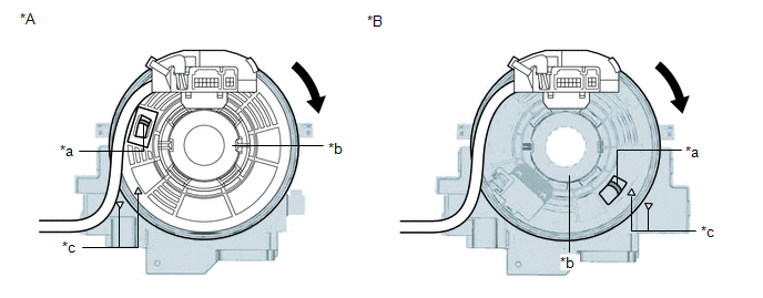
| *A | w/o Heated Steering Wheel System and Pre-collision System | *B | w/ Heated Steering Wheel System or Pre-collision System |
| *a | Flat Cable | *b | Interlock |
| *c | Alignment Mark | - | - |
HINT:
The spiral cable sub-assembly can be rotated approximately 2.5 turns to both the left and right from the center.
2. INSTALL SPIRAL CABLE SUB-ASSEMBLY
| (a) Align the 2 pins and 2 guides, and engage the 6 claws to install the spiral cable sub-assembly to the steering sensor. NOTICE:
|
|
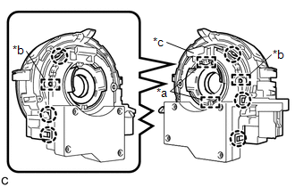
| (b) Remove the lock pin from the steering sensor. |
|
.png)
3. INSTALL SPIRAL CABLE WITH SENSOR SUB-ASSEMBLY
NOTICE:
- Do not replace the spiral cable with sensor sub-assembly with the battery connected and the engine switch on (IG).
- Do not rotate the spiral cable with sensor sub-assembly without the steering wheel assembly installed, with the battery connected and the engine switch on (IG).
- Ensure that the steering wheel assembly is installed and aligned straight when inspecting the steering sensor.
(a) Check that the engine switch is off.
(b) Check that the cable is disconnected from the negative (-) battery terminal.
CAUTION:
Wait at least 90 seconds after disconnecting the cable from the negative (-) battery terminal to disable the SRS system.
.png)
(c) Check that the front wheels are aligned facing straight ahead.
(d) Engage the 3 claws to install the spiral cable with sensor sub-assembly.
(e) Connect each connector.
4. INSTALL UPPER STEERING COLUMN COVER
Click here .gif)
5. INSTALL LOWER STEERING COLUMN COVER
Click here
6. ALIGN FRONT WHEELS FACING STRAIGHT AHEAD
7. INSPECT AND ADJUST SPIRAL CABLE WITH SENSOR SUB-ASSEMBLY
NOTICE:
Do not adjust the spiral cable with sensor sub-assembly with the battery connected and the engine switch on (IG).
(a) Check that the engine switch is off.
(b) Check that the cable is disconnected from the negative (-) battery terminal.
CAUTION:
Wait at least 90 seconds after disconnecting the cable from the negative (-) battery terminal to disable the SRS system.
| (c) Check if the spiral cable with sensor sub-assembly is centered. HINT: When the spiral cable with sensor sub-assembly is centered, the part (A) is positioned at the top and the flat cable shown in the illustration is visible. |
|
(d) If the spiral cable with sensor sub-assembly is not centered, center it.
| (1) While pushing on the interlock shown in the illustration, rotate the spiral cable with sensor sub-assembly counterclockwise slowly by hand until it stops. NOTICE:
|
|
| (2) While pushing on the interlock shown in the illustration, rotate the spiral cable with sensor sub-assembly clockwise approximately 2.5 times to the position where the alignment marks are aligned and the flat cable shown in the illustration is visible. HINT: The spiral cable with sensor sub-assembly will rotate approximately 2.5 times to both the left and right from the center. |
|
8. INSTALL STEERING WHEEL ASSEMBLY
Click here
9. CUSTOMIZE POWER TILT AND POWER TELESCOPIC STEERING COLUMN SYSTEM
Click here
10. ADJUST PARKING ASSIST MONITOR SYSTEM
for Initialization: Click here
for Calibration: Click here
11. ADJUST PANORAMIC VIEW MONITOR SYSTEM (w/ Panoramic View Monitor System)
for Initialization: Click here
for Calibration: Click here
12. ADJUST INTELLIGENT CLEARANCE SONAR SYSTEM (w/ Intelligent Clearance Sonar System)
Click here
 Inspection
INSPECTION PROCEDURE 1. INSPECT SPIRAL CABLE SUB-ASSEMBLY NOTICE:
Do not remove the steering sensor from the spiral cable sub-assembly when inspecting the spiral cable sub-assembly.
Remove the st ...
 Steering Pad
...
Other materials:
Lexus RX (RX 350L, RX450h) 2016-2026 Repair Manual > Sfi System: Fuel Rail Pressure Sensor (Low) / Fuel Rail Pressure Sensor "B" Circuit Short to Battery or Open (P107A15)
DESCRIPTION Refer to DTC P107A11. Click here DTC No. Detection Item DTC Detection Condition Trouble Area MIL Memory Note P107A15 Fuel Rail Pressure Sensor (Low) / Fuel Rail Pressure Sensor "B" Circuit Short to Battery or Open The fuel pressure sensor (for low pressure side) ...
Lexus RX (RX 350L, RX450h) 2016-2026 Repair Manual > Back Door Outside Garnish: Components
COMPONENTS ILLUSTRATION *A w/o Rear No. 2 Seat *B w/ Rear No. 2 Seat *1 BACK DOOR LOCK COVER *2 BACK DOOR TRIM BASE *3 BACK DOOR TRIM COVER LH *4 BACK DOOR TRIM COVER RH *5 BACK DOOR TRIM PANEL ASSEMBLY *6 BACK WINDOW UPPER PANEL TRIM *7 DOOR PULL HANDLE ...
Lexus RX (RX 350L, RX450h) 2016-{YEAR} Owners Manual
- For your information
- Pictorial index
- For safety and security
- Instrument cluster
- Operation of each component
- Driving
- Lexus Display Audio system
- Interior features
- Maintenance and care
- When trouble arises
- Vehicle specifications
- For owners
Lexus RX (RX 350L, RX450h) 2016-{YEAR} Repair Manual

0.0123