Lexus RX (RX 350L, RX450h) 2016-2026 Repair Manual: Electrical Key Oscillator(for Rear Floor)
Components
COMPONENTS
ILLUSTRATION
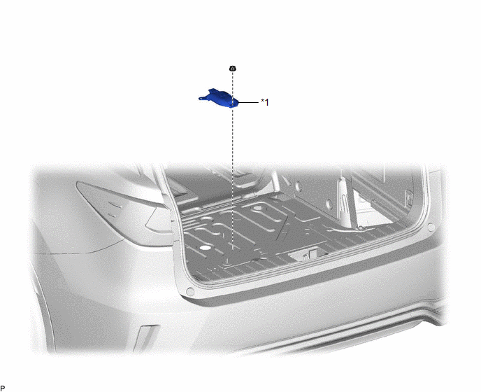
| *1 | NO. 3 INDOOR ELECTRICAL KEY ANTENNA ASSEMBLY | - | - |
Removal
REMOVAL
PROCEDURE
1. REMOVE REAR NO. 2 SEAT ASSEMBLY
Click here .gif)
2. REMOVE NO. 3 INDOOR ELECTRICAL KEY ANTENNA ASSEMBLY
(a) Turn back the rear floor carpet assembly.
(b) Disconnect the connector.
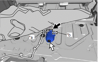
| *a | Clamp (A) |
| *b | Clamp (B) |
.png) | Connector |
.png) | Nut |
(c) Disengage the clamp (A).
(d) Remove the nut.
(e) Disengage the clamp (B) to remove the No. 3 indoor electrical key antenna assembly.
NOTICE:
Be careful when removing the No. 3 indoor electrical key antenna assembly. If the No. 3 indoor electrical key antenna assembly is dropped, replace it with a new one.
Installation
INSTALLATION
PROCEDURE
1. INSTALL NO. 3 INDOOR ELECTRICAL KEY ANTENNA ASSEMBLY
(a) Engage the clamp (B) to install the No. 3 indoor electrical key antenna assembly.
NOTICE:
Be careful when installing the No. 3 indoor electrical key antenna assembly. If the No. 3 indoor electrical key antenna assembly is dropped, replace it with a new one.
.png)
| *a | Clamp (A) |
| *b | Clamp (B) |
.png) | Connector |
.png) | Nut |
(b) Install the nut.
(c) Engage the clamp (A) and connect the connector.
(d) Install the floor carpet.
2. INSTALL REAR NO. 2 SEAT ASSEMBLY
Click here .gif)
 Installation
INSTALLATION PROCEDURE 1. INSTALL NO. 3 INDOOR ELECTRICAL KEY ANTENNA ASSEMBLY (a) Engage the clamp to install the No. 3 indoor electrical key antenna assembly as shown in the illustration. Ins ...
 Engine Hood Courtesy Switch
ComponentsCOMPONENTS ILLUSTRATION *1 COOL AIR INTAKE DUCT SEAL *2 ENGINE HOOD COURTESY SWITCH (HOOD LOCK ASSEMBLY) *3 HOOD LOCK RELEASE LEVER PROTECTOR - - N*m (kgf*cm, ft.* ...
Other materials:
Lexus RX (RX 350L, RX450h) 2016-2026 Repair Manual > Navigation System: Freeze Frame Data
FREEZE FRAME DATA CHECK FREEZE FRAME DATA (a) Connect the Techstream to the DLC3. (b) Turn the engine switch on (IG). (c) Turn the Techstream on. (d) Enter the following menus: Body Electrical / Navigation System / Trouble Codes. Body Electrical > Navigation System > Trouble Codes (e) Select a ...
Lexus RX (RX 350L, RX450h) 2016-2026 Repair Manual > Seat Heater System: How To Proceed With Troubleshooting
CAUTION / NOTICE / HINT HINT:
Use the following procedure to troubleshoot the seat heater system.
*: Use the Techstream.
PROCEDURE 1. VEHICLE BROUGHT TO WORKSHOP
NEXT 2. CUSTOMER PROBLEM ANALYSIS (a) Interview the customer to confirm the problem. Click here ...
Lexus RX (RX 350L, RX450h) 2016-{YEAR} Owners Manual
- For your information
- Pictorial index
- For safety and security
- Instrument cluster
- Operation of each component
- Driving
- Lexus Display Audio system
- Interior features
- Maintenance and care
- When trouble arises
- Vehicle specifications
- For owners
Lexus RX (RX 350L, RX450h) 2016-{YEAR} Repair Manual

0.0113