Lexus RX (RX 350L, RX450h) 2016-2026 Repair Manual: Telephone Sub Antenna Circuit Short to Ground (B153711,B153713)
DESCRIPTION
These DTCs are stored when a malfunction occurs in the telephone and GPS antenna (for Front Side).
| DTC No. | Detection Item | DTC Detection Condition | Trouble Area |
|---|---|---|---|
| B153711 | Telephone Sub Antenna Circuit Short to Ground | Telephone antenna (sub) impedance (Ω) is lower than the malfunction threshold for 10 seconds or more when the engine switch is on (IG) (Short circuit) |
|
| B153713 | Telephone Sub Antenna Circuit Open | Telephone antenna (sub) impedance (Ω) is higher than the malfunction threshold for 10 seconds or more when the engine switch is on (IG) (Open circuit) |
|
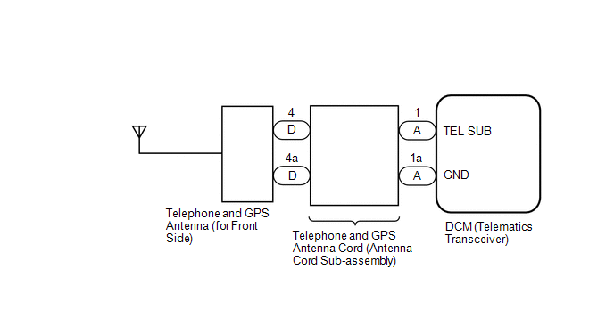
WIRING DIAGRAM
CAUTION / NOTICE / HINT
NOTICE:
Depending on the parts that are replaced during vehicle inspection or maintenance, performing initialization, registration or calibration may be needed. Refer to Precaution for Safety Connect System.
Click here .gif)
HINT:
Refer to "PARTS LOCATION" for the installation location of telephone and GPS antenna cord.
Click here
PROCEDURE
| 1. | CHECK DTC |
(a) Turn the engine switch off.
(b) Connect the Techstream to the DLC3.
(c) Turn the engine switch on (IG) and wait for 10 seconds or more.
(d) Turn the Techstream on.
(e) Clear the DTCs.
Body Electrical > Telematics > Clear DTCs(f) Check for DTCs and check that no DTCs are output.
Body Electrical > Telematics > Trouble CodesOK:
No DTCs are output.
| OK |  | USE SIMULATION METHOD TO CHECK |
|

| 2. | INSPECT TELEPHONE AND GPS ANTENNA (FOR FRONT SIDE) |
(a) Remove the telephone and GPS antenna (for Front Side).
Click here
(b) Inspect the telephone and GPS antenna (for Front Side).
Click here
| NG | | REPLACE TELEPHONE AND GPS ANTENNA (FOR FRONT SIDE) |
|
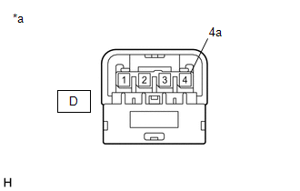
| 3. | INSPECT TELEPHONE AND GPS ANTENNA CORD (ANTENNA CORD SUB-ASSEMBLY) |
| (a) Disconnect the antenna connector from the telephone and GPS antenna (for Front Side). |
|
| (b) Disconnect the antenna connector from the DCM (telematics transceiver). |
|
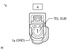
(c) Measure the resistance according to the value(s) in the table below.
Standard Resistance:
| Tester Connection | Condition | Specified Condition |
|---|---|---|
| A-1 (TEL SUB) - D-4 | Always | Below 1 Ω |
| A-1a (GND) - D-4a | Always | Below 1 Ω |
| A-1 (TEL SUB) or D-4 - Body ground | Always | 10 kΩ or higher |
| NG | | REPLACE TELEPHONE AND GPS ANTENNA CORD (ANTENNA CORD SUB-ASSEMBLY) |
|
| 4. | REPLACE DCM (TELEMATICS TRANSCEIVER) |
(a) Replace the DCM (telematics transceiver) with a new one.
Click here
NOTICE:
- The engine switch must be off.
- Do not exchange the DCM (telematics transceiver) with one from another vehicle.
| NEXT | | PERFORM DCM ACTIVATION |
 Vehicle Control History
VEHICLE CONTROL HISTORY NOTICE: Make sure to record any output Vehicle Control History codes before clearing them and checking the Vehicle Control History again. CHECK VEHICLE CONTROL HISTORY NOTICE: ...
 Indicator (Red) Circuit Short to Ground (B157011,B157013)
DESCRIPTION This DTC is stored when the DCM (telematics transceiver) detects an open or short in the manual (SOS) switch red indicator circuit of the manual (SOS) switch. The manual (SOS) switch red i ...
Other materials:
Lexus RX (RX 350L, RX450h) 2016-2026 Repair Manual > Rear No. 2 Seat Assembly: Disassembly
DISASSEMBLY CAUTION / NOTICE / HINT CAUTION: Wear protective gloves. Sharp areas on the seat frame may injure your hands. PROCEDURE 1. REMOVE SEAT ADJUSTER COVER CAP (a) Remove the 2 seat adjuster cover caps. 2. REMOVE REAR SEAT HEADREST ASSEMBLY (a) Remove the 2 rear seat headrest as ...
Lexus RX (RX 350L, RX450h) 2016-2026 Repair Manual > Smart Access System With Push-button Start (for Entry Function): Operation History List
OPERATION HISTORY LIST NOTICE:
The cause of a malfunction is stored in the RAM or EEPROM in the certification ECU (smart key ECU assembly). As the cause of a malfunction stored in the RAM will be cleared when the cable is disconnected from the negative (-) battery terminal, do not disconnect the ...
Lexus RX (RX 350L, RX450h) 2016-{YEAR} Owners Manual
- For your information
- Pictorial index
- For safety and security
- Instrument cluster
- Operation of each component
- Driving
- Lexus Display Audio system
- Interior features
- Maintenance and care
- When trouble arises
- Vehicle specifications
- For owners
Lexus RX (RX 350L, RX450h) 2016-{YEAR} Repair Manual

0.0116