
Lexus RX (RX 350L, RX450h) 2016-2024 Repair Manual: Telephone And Gps Antenna Cords(w/ Rear No.2 Seat)
Components
COMPONENTS
ILLUSTRATION
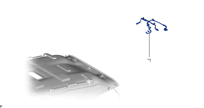
| *1 | TELEPHONE AND GPS ANTENNA CORD | - | - |
Removal
REMOVAL
CAUTION / NOTICE / HINT
The necessary procedures (adjustment, calibration, initialization, or registration) that must be performed after parts are removed and installed, or replaced during telephone and GPS antenna cord removal/installation are shown below.
Necessary Procedures After Parts Removed/Installed/Replaced| Replaced Part or Performed Procedure | Necessary Procedure | Effect/Inoperative Function when Necessary Procedure not Performed | Link |
|---|---|---|---|
|
*1: When performing learning using the Techstream.
Click here | |||
| Disconnect cable from negative battery terminal | Memorize steering angle neutral point | Lane Control System | |
| Pre-collision System | |||
| Intelligent Clearance Sonar System*1 | |||
| Parking Assist Monitor System | | ||
| Panoramic View Monitor System | | ||
| Lighting System (w/ Automatic Headlight Beam Level Control System) | | ||
| Initialize back door lock | Power Door Lock Control System | | |
| Reset back door close position | Power Back Door System (w/ Outside Door Control Switch) | | |
CAUTION:
Some of these service operations affect the SRS airbag system. Read the precautionary notices concerning the SRS airbag system before servicing.
Click here .gif)
.png)
PROCEDURE
1. REMOVE ROOF HEADLINING ASSEMBLY
Click here
2. REMOVE TELEPHONE AND GPS ANTENNA CORD
Click here
 Installation
INSTALLATION PROCEDURE 1. INSTALL TELEPHONE AND GPS ANTENNA ASSEMBLY (a) When reusing the telephone and GPS antenna assembly: (1) Install a new seal. (b) Push the telephone and GPS antenna assembly in ...
 Telephone And Gps Antenna Cords(w/o Rear No. 2 Seat)
ComponentsCOMPONENTS ILLUSTRATION *1 TELEPHONE AND GPS ANTENNA CORD - - RemovalREMOVAL CAUTION / NOTICE / HINT The necessary procedures (adjustment, calibration, initialization, or regist ...
Other materials:
Lexus RX (RX 350L, RX450h) 2016-2024 Repair Manual > Intake System: Parts Location
PARTS LOCATION ILLUSTRATION *1 INTAKE AIR CONTROL VALVE (for ACIS) *2 ECM *3 ENGINE ROOM RELAY BLOCK AND JUNCTION BLOCK ASSEMBLY - EFI NO. 2 FUSE - - ...
Lexus RX (RX 350L, RX450h) 2016-2024 Repair Manual > Front Drive Shaft Assembly: Components
COMPONENTS ILLUSTRATION *1 FRONT FENDER APRON SEAL LH *2 FRONT WHEEL OPENING EXTENSION PAD LH *3 NO. 3 ENGINE UNDER COVER - - ILLUSTRATION *A w/o AVS *B w/ AVS *1 FRONT AXLE SHAFT NUT *2 FRONT DRIVE SHAFT ASSEMBLY *3 FRONT LOWER NO. 1 SUSPENSION ARM S ...
Lexus RX (RX 350L, RX450h) 2016-{YEAR} Owners Manual
- For your information
- Pictorial index
- For safety and security
- Instrument cluster
- Operation of each component
- Driving
- Lexus Display Audio system
- Interior features
- Maintenance and care
- When trouble arises
- Vehicle specifications
- For owners
Lexus RX (RX 350L, RX450h) 2016-{YEAR} Repair Manual

0.013