Lexus RX (RX 350L, RX450h) 2016-2026 Repair Manual: Extension Module Disconnected 2 (B1543)
DESCRIPTION
If the radio receiver assembly cannot detect the navigation ECU for a certain period of time (90 seconds) after the engine switch is turned on (ACC) and the radio receiver assembly confirms that the information is missing by checking past navigation ECU recognition information (registered information), this DTC will be stored.
HINT:
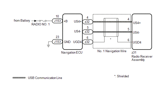
The Navigation system uses USB communication between devices. If an open, short, short to +B or short to ground occurs in the USB circuit, communication is interrupted and the Navigation system will not operate normally.
| DTC No. | Detection Item | DTC Detection Condition | Trouble Area |
|---|---|---|---|
| B1543 | Extension Module Disconnected 2 | Navigation ECU disconnected |
|
HINT:
This DTC may be stored due to environmental reasons such as electrical noise or interference.
WIRING DIAGRAM
CAUTION / NOTICE / HINT
NOTICE:
-
Depending on the parts that are replaced during vehicle inspection or maintenance, performing initialization, registration or calibration may be needed. Refer to Precaution for Navigation System.
Click here
.gif)
- Inspect the fuse for circuits related to this system before performing the following procedure.
PROCEDURE
| 1. | CHECK MAP SCREEN |
(a) Turn the engine switch on (ACC) and wait for 90 seconds.
(b) Press the "MAP" switch and check that the map screen is displayed normally.
| Result | Proceed to |
|---|---|
| Map screen is displayed normally | A |
| Map screen is not displayed normally | B |
HINT:
- This DTC may be stored due to environmental reasons such as electrical noise or interference.
- Clear past DTCs when the map screen is displayed normally. (Codes stored due to past environmental factors)
| A | .gif) | USE SIMULATION METHOD TO CHECK |
|
.gif)
| 2. | CHECK DTC |
(a) Clear the DTCs.
Body Electrical > Navigation System > Clear DTCs(b) Turn the engine switch off.
(c) Turn the engine switch on (IG) and wait for 90 seconds.
(d) Recheck for DTCs and check that no DTCs are output.
Body Electrical > Navigation System > Trouble CodesOK:
No DTCs are output.
| OK | | USE SIMULATION METHOD TO CHECK |
|
| 3. | CHECK HARNESS AND CONNECTOR (NAVIGATION ECU POWER SOURCE) |
| (a) Disconnect the J153 navigation ECU connector. |
|
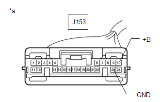
(b) Measure the resistance according to the value(s) in the table below.
Standard Resistance:
| Tester Connection | Condition | Specified Condition |
|---|---|---|
| J153-23 (GND) - Body ground | Always | Below 1 Ω |
(c) Measure the voltage according to the value(s) in the table below.
Standard Voltage:
| Tester Connection | Condition | Specified Condition |
|---|---|---|
| J153-10 (+B) - Body ground | Always | 11 to 14 V |
| NG | | REPAIR OR REPLACE HARNESS OR CONNECTOR |
|
| 4. | CHECK NO. 1 NAVIGATION WIRE (RADIO RECEIVER ASSEMBLY - NAVIGATION ECU) |
| (a) Disconnect the z31 radio receiver assembly connector. |
|
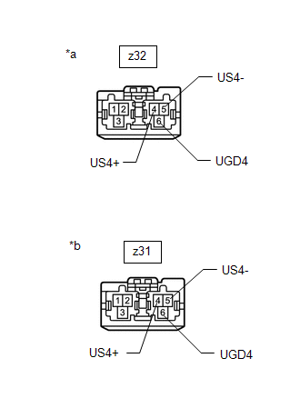
(b) Disconnect the z32 navigation ECU connector.
(c) Measure the resistance according to the value(s) in the table below.
Standard Resistance:
| Tester Connection | Condition | Specified Condition |
|---|---|---|
| z31-4 (US4+) - z32-4 (US4+) | Always | Below 1 Ω |
| z31-5 (US4-) - z32-5 (US4-) | Always | Below 1 Ω |
| z31-6 (UGD4) - z32-6 (UGD4) | Always | Below 1 Ω |
| NG | | REPLACE NO. 1 NAVIGATION WIRE |
|
| 5. | REPLACE NAVIGATION ECU |
(a) Replace the navigation ECU with a new or known good one.
Click here
|
| 6. | CHECK DTC |
(a) Clear the DTCs.
Body Electrical > Navigation System > Clear DTCs(b) Turn the engine switch off.
(c) Turn the engine switch on (IG) and wait for 90 seconds.
(d) Recheck for DTCs and check that no DTCs are output.
Body Electrical > Navigation System > Trouble CodesOK:
No DTCs are output.
| OK | | END (NAVIGATION ECU IS DEFECTIVE) |
| NG | | REPLACE RADIO RECEIVER ASSEMBLY |
 Operation Check
OPERATION CHECK CHECK NAVIGATION SYSTEM NORMAL CONDITION (a) If the cause of a symptom is any of the following, the corresponding symptom is normal; it is not due to a malfunction. Symptom Answer ...
 HD Radio Tuner Malfunction (B1551,B15A0,B15B3-B15B5,B15B7,B15BA,B15F9)
DESCRIPTION These DTCs are stored when a malfunction occurs in the radio receiver assembly DTC No. Detection Item DTC Detection Condition Trouble Area B1551 HD Radio Tuner Malfunction ...
Other materials:
Lexus RX (RX 350L, RX450h) 2016-2026 Owners Manual > Other function: USB photo
Connecting a USB memory device enables you to enjoy photo on the Lexus
Display Audio display.
USB photo screen
Go to "USB Photo": "MENU" button → "Info" → "USB1 Photo" or "USB2
Photo"
Menu screen
Move the controller to the left to display the menu screen.
Change the full screen mode.
...
Lexus RX (RX 350L, RX450h) 2016-2026 Repair Manual > Sliding Roof Housing (for Panoramic Moon Roof): Removal
REMOVAL CAUTION / NOTICE / HINT The necessary procedures (adjustment, calibration, initialization or registration) that must be performed after parts are removed and installed, or replaced during sliding roof glass sub-assembly, sliding roof housing panel, sliding roof drive gear assembly, sliding r ...
Lexus RX (RX 350L, RX450h) 2016-{YEAR} Owners Manual
- For your information
- Pictorial index
- For safety and security
- Instrument cluster
- Operation of each component
- Driving
- Lexus Display Audio system
- Interior features
- Maintenance and care
- When trouble arises
- Vehicle specifications
- For owners
Lexus RX (RX 350L, RX450h) 2016-{YEAR} Repair Manual

0.0112