Lexus RX (RX 350L, RX450h) 2016-2024 Repair Manual: Multi-axis Acceleration Sensor Module "A" Supply Voltage Circuit Voltage Out of Range (C14D71C)
DESCRIPTION
-
The airbag sensor assembly has a built-in yaw rate and acceleration sensor and detects the vehicle condition.
This DTC is stored when the skid control ECU (brake actuator assembly) receives a sensor supply voltage malfunction signal from the acceleration sensor (airbag sensor assembly).
This DTC may be stored due to an intermittent low power source voltage.
-
This DTC is stored when the skid control ECU (brake actuator assembly) receives a sensor supply voltage malfunction signal from the yaw rate and acceleration sensor.
This DTC may be stored due to an intermittent low power source voltage.
| DTC No. | Detection Item | DTC Detection Condition | Trouble Area |
|---|---|---|---|
| C14D71C | Multi-axis Acceleration Sensor Module "A" Supply Voltage Circuit Voltage Out of Range | When the +BS terminal voltage is from 9.5 to 17.4 V at a vehicle speed exceeding 3 km/h (2 mph), an acceleration sensor power source malfunction signal is received for 10 seconds or more. |
|
WIRING DIAGRAM
for Optitron Meter Type: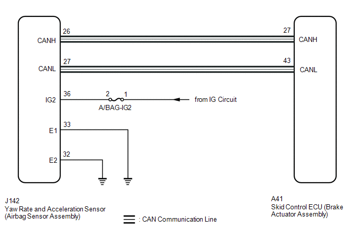 for TFT Meter Type:
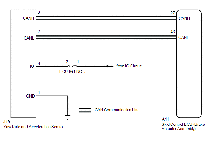
CAUTION / NOTICE / HINT
NOTICE:
- Inspect the fuses for circuits related to this system before performing the following procedure.
-
If the yaw rate and acceleration sensor (airbag sensor assembly) was replaced or reinstalled, perform "Calibration". (for Optitron Meter Type)
If the yaw rate and acceleration sensor was replaced or reinstalled, perform "Calibration". (for TFT Meter Type)
Click here
.gif)
PROCEDURE
| 1. | CHECK VEHICLE SPECIFICATION |
(a) Check the combination meter assembly.
Click here
| Result | Proceed to |
|---|---|
| for Optitron Meter Type | A |
| for TFT Meter Type | B |
| B | .gif) | GO TO STEP 6 |
|
.gif)
| 2. | CHECK HARNESS AND CONNECTOR (IG2 TERMINAL) |
| (a) Disconnect the cable from the negative (-) battery terminal, and wait for at least 90 seconds. |
|
(b) Make sure that there is no looseness at the locking part and the connecting part of the connectors.
OK:
The connector is securely connected.
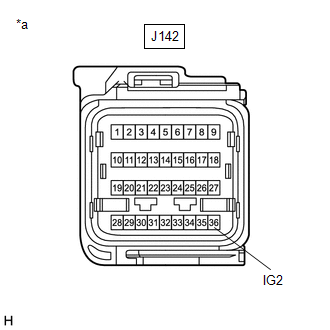
(c) Disconnect the J142 yaw rate and acceleration sensor (airbag sensor assembly) connector.
(d) Check both the connector case and the terminals for deformation and corrosion.
OK:
No deformation or corrosion.
(e) Connect the cable to the negative (-) battery terminal.
(f) Turn the engine switch on (IG).
(g) Measure the voltage according to the value(s) in the table below.
Standard Voltage:
| Tester Connection | Condition | Specified Condition |
|---|---|---|
| J142-36 (IG2) - Body ground | Engine switch on (IG) | 11 to 14 V |
| NG | | REPAIR OR REPLACE HARNESS OR CONNECTOR |
|
| 3. | CHECK HARNESS AND CONNECTOR (E1 AND E2 TERMINAL) |
(a) Turn the engine switch off.
(b) Measure the resistance according to the value(s) in the table below.
Standard Resistance:
| Tester Connection | Condition | Specified Condition |
|---|---|---|
| J142-33 (E1) - Body ground | 1 minute or more after disconnecting the cable from the negative (-) battery terminal | Below 1 Ω |
| J142-32 (E2) - Body ground | 1 minute or more after disconnecting the cable from the negative (-) battery terminal | Below 1 Ω |
| NG | | REPAIR OR REPLACE HARNESS OR CONNECTOR |
|
| 4. | CLEAR DTC |
(a) Reconnect the J142 yaw rate and acceleration sensor (airbag sensor assembly) connector.
(b) Connect the Techstream to the DLC3.
(c) Turn the engine switch on (IG).
(d) Operate the Techstream to clear the codes. Enter the following menus: Chassis / Brake/EPB / Trouble Codes.
Chassis > Brake/EPB > Clear DTCs(e) Press the DTC clear button.
(f) Turn the engine switch off.
|
| 5. | RECONFIRM DTC |
(a) Start the engine.
(b) Perform a road test.
(c) Read the DTCs following the prompts on the Techstream. Enter the following menus: Chassis / Brake/EPB / Trouble Codes.
Chassis > Brake/EPB > Trouble Codes(d) Check if the same DTC is output.
| Result | Proceed to |
|---|---|
| DTC C14D71C is not output. | A |
| DTC C14D71C is output. | B |
| A | | USE SIMULATION METHOD TO CHECK |
| B | | REPLACE AIRBAG SENSOR ASSEMBLY |
| 6. | CHECK HARNESS AND CONNECTOR (IG TERMINAL) |
| (a) Make sure that there is no looseness at the locking part and the connecting part of the connectors. OK: The connector is securely connected. |
|
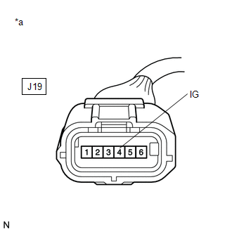
(b) Disconnect the J19 yaw rate and acceleration sensor connector.
(c) Check both the connector case and the terminals for deformation and corrosion.
OK:
No deformation or corrosion.
(d) Turn the engine switch on (IG).
(e) Measure the voltage according to the value(s) in the table below.
Standard Voltage:
| Tester Connection | Condition | Specified Condition |
|---|---|---|
| J19-4 (IG) - Body ground | Engine switch on (IG) | 11 to 14 V |
| NG | | REPAIR OR REPLACE HARNESS OR CONNECTOR |
|
| 7. | CHECK HARNESS AND CONNECTOR (GND TERMINAL) |
(a) Turn the engine switch off.
(b) Measure the resistance according to the value(s) in the table below.
Standard Resistance:
| Tester Connection | Condition | Specified Condition |
|---|---|---|
| J19-1 (GND) - Body ground | 1 minute or more after disconnecting the cable from the negative (-) battery terminal | Below 1 Ω |
| NG | | REPAIR OR REPLACE HARNESS OR CONNECTOR |
|
| 8. | CLEAR DTC |
(a) Reconnect the J19 yaw rate and acceleration sensor connector.
(b) Connect the Techstream to the DLC3.
(c) Turn the engine switch on (IG).
(d) Operate the Techstream to clear the codes. Enter the following menus: Chassis / Brake/EPB / Trouble Codes.
Chassis > Brake/EPB > Clear DTCs(e) Press the DTC clear button.
(f) Turn the engine switch off.
|
| 9. | RECONFIRM DTC |
(a) Start the engine.
(b) Perform a road test.
(c) Read the DTCs following the prompts on the Techstream. Enter the following menus: Chassis / Brake/EPB / Trouble Codes.
Chassis > Brake/EPB > Trouble Codes(d) Check if the same DTC is output.
| Result | Proceed to |
|---|---|
| DTC C14D71C is not output. | A |
| DTC C14D71C is output. | B |
| A | | USE SIMULATION METHOD TO CHECK |
| B | | REPLACE YAW RATE AND ACCELERATION SENSOR |
 ABS Pump Motor Actuator Stuck (C142771)
DESCRIPTION DTC No. Detection Item DTC Detection Condition Trouble Area C142771 ABS Pump Motor Actuator Stuck Actuator pump motor does not operate properly.
Wire harness and conn ...
 Left Front Wheel Speed Sensor Supply Voltage Circuit Short to Ground or Open (C14E014,C14E314)
DESCRIPTION Refer to DTC C05001F. Click here DTC No. Detection Item DTC Detection Condition Trouble Area C14E014 Left Front Wheel Speed Sensor Supply Voltage Circuit Short to Ground o ...
Other materials:
Lexus RX (RX 350L, RX450h) 2016-2024 Repair Manual > Audio And Visual System (for 12.3 Inch Display): Does not Play even after Bluetooth Audio Mode is Selected
CAUTION / NOTICE / HINT NOTICE: Depending on the parts that are replaced during vehicle inspection or maintenance, performing initialization, registration or calibration may be needed. Refer to Precaution for Audio and Visual System. Click here HINT: Even if the portable player can play audio cont ...
Lexus RX (RX 350L, RX450h) 2016-2024 Repair Manual > Shift Paddle Switch: Removal
REMOVAL CAUTION / NOTICE / HINT The necessary procedures (adjustment, calibration, initialization or registration) that must be performed after parts are removed and installed, or replaced during shift paddle switch (transmission shift switch assembly) removal/installation are shown below. Necessary ...
Lexus RX (RX 350L, RX450h) 2016-{YEAR} Owners Manual
- For your information
- Pictorial index
- For safety and security
- Instrument cluster
- Operation of each component
- Driving
- Lexus Display Audio system
- Interior features
- Maintenance and care
- When trouble arises
- Vehicle specifications
- For owners
Lexus RX (RX 350L, RX450h) 2016-{YEAR} Repair Manual

0.0148