Lexus RX (RX 350L, RX450h) 2016-2026 Repair Manual: Display does not Dim when Light Control Switch is Turned ON
DESCRIPTION
When the navigation system is activated with the light control switch in the tail or head position, before AVC-LAN communication is established, the multi-display assembly dims the display according to the illumination signal received via a direct line.
After AVC-LAN communication is established, the multi-display assembly dims the display according to a dimmer signal sent via AVC-LAN communication.
The radio receiver assembly switches between the daytime screen and night screen on the multi-display assembly according to the illumination signal input.
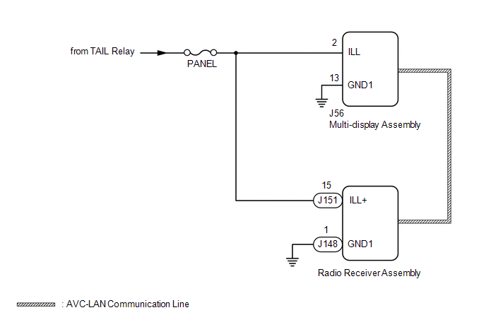
WIRING DIAGRAM
CAUTION / NOTICE / HINT
NOTICE:
Inspect the fuses for circuits related to this system before performing the following procedure.
PROCEDURE
| 1. | CHECK SYMPTOMS |
(a) Check the symptoms that occur by viewing the display.
| Result | Proceed to |
|---|---|
| There is a delay until the display dims after the navigation system is activated with the light control switch in the tail or head position. | A |
| The display dims for a moment and then becomes bright after the navigation system is activated with the light control switch in the tail or head position. | B |
| When the light control switch is set to the tail or head position, the display dims but does not switch to the night screen. | |
| When the light control switch is set to the tail or head position, the display neither dims nor switches to the night screen. | C |
HINT:
- When the navigation system is activated with the light control switch in the tail or head position, before AVC-LAN communication is established, the multi-display assembly dims the display according to the illumination signal received via a direct line.
- After AVC-LAN communication is established, the multi-display assembly dims the display according to a dimmer signal sent via AVC-LAN communication.
- The radio receiver assembly switches between the daytime screen and night screen on the multi-display assembly according to the illumination signal input.
| B |  | GO TO STEP 3 |
| C | | GO TO LIGHTING SYSTEM |
|

| 2. | CHECK HARNESS AND CONNECTOR (ILLUMINATION SIGNAL) |
(a) Disconnect the J56 multi-display assembly connector.
(b) Measure the resistance according to the value(s) in the table below.
Standard Resistance:
| Tester Connection | Condition | Specified Condition |
|---|---|---|
| J56-13 (GND1) - Body ground | Always | Below 1 Ω |
(c) Measure the voltage according to the value(s) in the table below.
Standard Voltage:
| Tester Connection | Condition | Specified Condition |
|---|---|---|
| J56-2 (ILL) - J56-13 (GND1) | Light control switch in tail or head position | 11 to 14 V |
| OK | | PROCEED TO NEXT SUSPECTED AREA SHOWN IN PROBLEM SYMPTOMS TABLE |
| NG | | REPAIR OR REPLACE HARNESS OR CONNECTOR |
| 3. | CHECK IMAGE QUALITY SETTING |
(a) Turn the light control switch to the tail or head position.
(b) Check that the daytime screen setting on the display adjustment screen is set to on.
| Result | Proceed to |
|---|---|
| Daytime screen setting is set to on. | A |
| Daytime screen setting is set to off. | B |
| A | | CHANGE DAYTIME SCREEN SETTING TO OFF |
|
| 4. | CHECK VEHICLE SIGNAL (OPERATION CHECK) |
| (a) Enter the "Vehicle Signal Check Mode" screen. Refer to Check Vehicle Signal in Operation Check. Click here |
|
.gif)
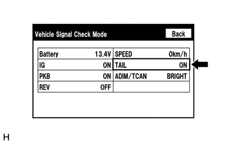
(b) Check that the display changes between ON and OFF according to the light control switch operation.
OK:
| Light Control Switch | Display |
|---|---|
| Tail or head | ON |
| Off or AUTO | OFF |
HINT:
- The display is updated once per second. It is normal for the display to lag behind the actual switch operation.
- Make sure to move the vehicle to a bright area before performing an operation check with the light control switch in the AUTO position.
| OK | | PROCEED TO NEXT SUSPECTED AREA SHOWN IN PROBLEM SYMPTOMS TABLE |
|
| 5. | CHECK HARNESS AND CONNECTOR (ILLUMINATION SIGNAL) |
(a) Disconnect the J151 and J148 radio receiver assembly connectors.
(b) Measure the resistance according to the value(s) in the table below.
Standard Resistance:
| Tester Connection | Condition | Specified Condition |
|---|---|---|
| J148-1 (GND1) - Body ground | Always | Below 1 Ω |
(c) Measure the voltage according to the value(s) in the table below.
Standard Voltage:
| Tester Connection | Condition | Specified Condition |
|---|---|---|
| J151-15 (ILL+) - J148-1 (GND1) | Light control switch in tail or head position | 11 to 14 V |
| OK | | PROCEED TO NEXT SUSPECTED AREA SHOWN IN PROBLEM SYMPTOMS TABLE |
| NG | | REPAIR OR REPLACE HARNESS OR CONNECTOR |
 Radio Broadcast cannot be Received or Poor Reception
CAUTION / NOTICE / HINT NOTICE: Depending on the parts that are replaced during vehicle inspection or maintenance, performing initialization, registration or calibration may be needed. Refer to Precau ...
 Panel Switches do not Function
CAUTION / NOTICE / HINT NOTICE: Depending on the parts that are replaced during vehicle inspection or maintenance, performing initialization, registration or calibration may be needed. Refer to Precau ...
Other materials:
Lexus RX (RX 350L, RX450h) 2016-2026 Repair Manual > Height Control Sensor: Removal
REMOVAL CAUTION / NOTICE / HINT The necessary procedures (adjustment, calibration, initialization or registration) that must be performed after parts are removed and installed, or replaced during height control sensor sub-assembly RH removal/installation are shown below. Necessary Procedures After P ...
Lexus RX (RX 350L, RX450h) 2016-2026 Repair Manual > Air Conditioning System: Parts Location
PARTS LOCATION ILLUSTRATION *A w/o Rear Air Conditioning System *B w/ PTC Heater *C w/ Smog Ventilation Sensor *D w/ Pre-collision System *1 AIR CONDITIONER PRESSURE SENSOR *2 COOLER (AMBIENT TEMP. SENSOR) THERMISTOR *3 COOLER COMPRESSOR ASSEMBLY *4 SEMICONDUC ...
Lexus RX (RX 350L, RX450h) 2016-{YEAR} Owners Manual
- For your information
- Pictorial index
- For safety and security
- Instrument cluster
- Operation of each component
- Driving
- Lexus Display Audio system
- Interior features
- Maintenance and care
- When trouble arises
- Vehicle specifications
- For owners
Lexus RX (RX 350L, RX450h) 2016-{YEAR} Repair Manual

0.0103