Lexus RX (RX 350L, RX450h) 2016-2026 Repair Manual: Radio Receiver Power Source Circuit
DESCRIPTION
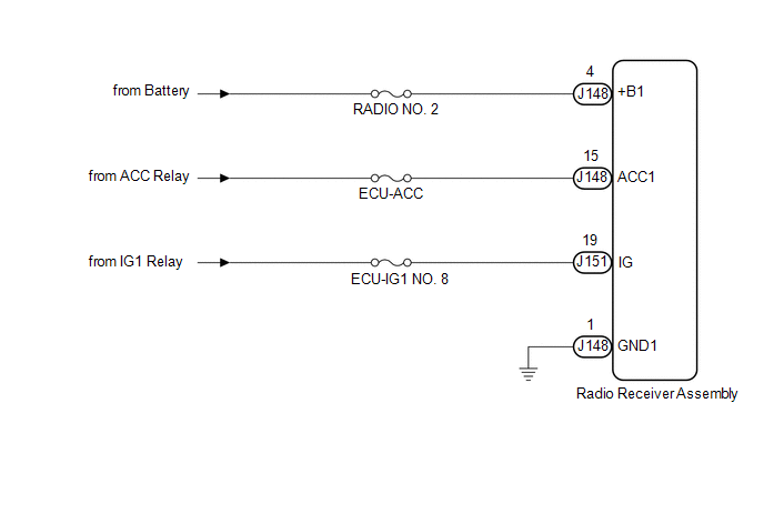
This is the power source circuit to operate the radio receiver assembly.
WIRING DIAGRAM
CAUTION / NOTICE / HINT
NOTICE:
Inspect the fuses for circuits related to this system before performing the following procedure.
PROCEDURE
| 1. | CHECK HARNESS AND CONNECTOR (RADIO RECEIVER ASSEMBLY POWER SOURCE) |
(a) Disconnect the J148 and J151 radio receiver assembly connectors.
(b) Measure the resistance according to the value(s) in the table below.
Standard Resistance:
| Tester Connection | Condition | Specified Condition |
|---|---|---|
| J148-1 (GND1) - Body ground | Always | Below 1 Ω |
(c) Measure the voltage according to the value(s) in the table below.
Standard Voltage:
| Tester Connection | Condition | Specified Condition |
|---|---|---|
| J148-4 (+B1) - J148-1 (GND1) | Always | 11 to 14 V |
| J148-15 (ACC1) - J148-1 (GND1) | Engine switch on (ACC) | 11 to 14 V |
| J151-19 (IG) - J148-1 (GND1) | Engine switch on (IG) | 11 to 14 V |
| OK | .gif) | PROCEED TO NEXT SUSPECTED AREA SHOWN IN PROBLEM SYMPTOMS TABLE |
| NG | | REPAIR OR REPLACE HARNESS OR CONNECTOR |
 Microphone Circuit
DESCRIPTION
The radio receiver assembly and telephone microphone assembly are connected to each other using the microphone connection detection signal lines.
Using this circuit, the DCM (telemati ...
 Visual Mute Signal Circuit between Radio Receiver and Multi-display
DESCRIPTION The radio receiver assembly sends a visual mute signal to the multi-display assembly. As a result, a black screen is displayed when the screen changes so that noise and distorted images ar ...
Other materials:
Lexus RX (RX 350L, RX450h) 2016-2026 Repair Manual > Accelerator Pedal: Installation
INSTALLATION PROCEDURE 1. INSTALL ACCELERATOR PEDAL (a) Install the accelerator pedal with the 2 bolts. Torque: 5.4 N·m {55 kgf·cm, 48 in·lbf} 2. INSTALL ACCELERATOR PEDAL PAD (a) Engage the 2 claws to install the accelerator pedal pad. 3. INSTALL ACCELERATOR PEDAL SENSOR ASSEMBLY NOTICE:
Avo ...
Lexus RX (RX 350L, RX450h) 2016-2026 Repair Manual > Sfi System: Engine Coolant Temperature Sensor 1 Signal Stuck in Range (P01152A)
DESCRIPTION Refer to DTC P011511. Click here DTC No. Detection Item DTC Detection Condition Trouble Area MIL Memory Note P01152A Engine Coolant Temperature Sensor 1 Signal Stuck in Range Either of the following conditions is met (2 trip detection logic):
When engine is st ...
Lexus RX (RX 350L, RX450h) 2016-{YEAR} Owners Manual
- For your information
- Pictorial index
- For safety and security
- Instrument cluster
- Operation of each component
- Driving
- Lexus Display Audio system
- Interior features
- Maintenance and care
- When trouble arises
- Vehicle specifications
- For owners
Lexus RX (RX 350L, RX450h) 2016-{YEAR} Repair Manual

0.0108