Lexus RX (RX 350L, RX450h) 2016-2026 Repair Manual: Short to GND in Outer Mirror Indicator(Master) (C1AB2)
DESCRIPTION
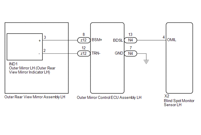
This DTC is stored when the blind spot monitor sensor LH detects a short to ground in the outer rear view mirror indicator LH.
| DTC No. | Detection Item | DTC Detection Condition | Trouble Area |
|---|---|---|---|
| C1AB2 | Short to GND in Outer Mirror Indicator(Master) | Both of the following conditions are met:
|
|
WIRING DIAGRAM
CAUTION / NOTICE / HINT
NOTICE:
When checking for DTCs, make sure that the blind spot monitor system is turned on.
PROCEDURE
| 1. | CHECK DTC |
(a) Turn the engine switch off.
(b) Turn the engine switch on (IG).
(c) Recheck for DTCs and check if the same DTC is output again.
Body Electrical > Blind Spot Monitor Master > Trouble CodesOK:
No DTCs are output.
| OK |  | USE SIMULATION METHOD TO CHECK |
|

| 2. | CHECK HARNESS AND CONNECTOR (BLIND SPOT MONITOR SENSOR LH - OUTER MIRROR CONTROL ECU ASSEMBLY LH) |
(a) Disconnect the X2 blind spot monitor sensor LH connector.
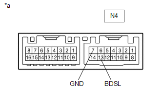
(b) Disconnect the N4 outer mirror control ECU assembly LH connector.
(c) Measure the resistance according to the value(s) in the table below.
Standard Resistance:
| Tester Connection | Condition | Always |
|---|---|---|
| X2-4 (OMIL) - Body ground | Always | 10 kΩ or higher |
| NG | | REPAIR OR REPLACE HARNESS OR CONNECTOR |
|
| 3. | INSPECT OUTER REAR VIEW MIRROR ASSEMBLY LH |
(a) Disconnect the z12 outer rear view mirror assembly LH connector.
(b) Disconnect the IND1 outer mirror LH connector.
(c) Measure the resistance according to the value(s) in the table below.
Standard Resistance:
| Tester Connection | Condition | Always |
|---|---|---|
| z12-8 (BSM+) - Body ground | Always | 10 kΩ or higher |
| NG | | REPLACE OUTER REAR VIEW MIRROR ASSEMBLY LH |
|
| 4. | INSPECT OUTER MIRROR CONTROL ECU ASSEMBLY LH |
| (a) Measure the resistance according to the value(s) in the table below. Standard Resistance:
|
|
| NG | | REPLACE OUTER MIRROR CONTROL ECU ASSEMBLY LH |
|
| 5. | INSPECT OUTER MIRROR LH |
(a) Remove the outer mirror LH.
Click here .gif)
(b) Inspect the outer rear view mirror indicator LH on the outer mirror LH.
Click here
| OK | | REPLACE BLIND SPOT MONITOR SENSOR LH |
| NG | | REPLACE OUTER MIRROR LH |
 Short to +B in Outer Mirror Indicator(Slave) (C1AB1)
DESCRIPTION This DTC is stored when the blind spot monitor sensor RH detects a short to +B in the outer rear view mirror indicator RH. DTC No. Detection Item DTC Detection Condition Trouble A ...
 Short to GND in Outer Mirror Indicator(Slave) (C1AB3)
DESCRIPTION This DTC is stored when the blind spot monitor sensor RH detects a short to ground in the outer rear view mirror indicator RH. DTC No. Detection Item DTC Detection Condition Troub ...
Other materials:
Lexus RX (RX 350L, RX450h) 2016-2026 Repair Manual > Exterior Panels / Trim: Wheel Opening Moulding(for Rear Side)
ComponentsCOMPONENTS ILLUSTRATION *1 QUARTER OUTSIDE MOULDING SUB-ASSEMBLY - - ● Non-reusable part - - RemovalREMOVAL CAUTION / NOTICE / HINT HINT:
Use the same procedure for the RH side and LH side.
The following procedure is for the LH side.
PROCEDURE 1. REMOVE QUA ...
Lexus RX (RX 350L, RX450h) 2016-2026 Repair Manual > Vehicle Stability Control System: Left Front Wheel Speed Sensor Signal Stuck Low (C050023)
DESCRIPTION Refer to DTC C05001F. Click here DTC No. Detection Item DTC Detection Condition Trouble Area C050023 Left Front Wheel Speed Sensor Signal Stuck Low Any of the following is detected:
When the +BS terminal voltage is 17.4 V or less at a vehicle speed of 10 km/h (6 mph ...
Lexus RX (RX 350L, RX450h) 2016-{YEAR} Owners Manual
- For your information
- Pictorial index
- For safety and security
- Instrument cluster
- Operation of each component
- Driving
- Lexus Display Audio system
- Interior features
- Maintenance and care
- When trouble arises
- Vehicle specifications
- For owners
Lexus RX (RX 350L, RX450h) 2016-{YEAR} Repair Manual

0.0134