Lexus RX (RX 350L, RX450h) 2016-2026 Repair Manual: Open or Short in Steering Angle Sensor +B (C1625)
DESCRIPTION
This DTC is stored if the clearance warning ECU assembly receives a signal via CAN communication from the steering sensor that indicates a power supply problem.
| DTC No. | Detection Item | DTC Detection Condition | Trouble Area |
|---|---|---|---|
| C1625 | Open or Short in Steering Angle Sensor +B | Open or short in steering sensor power source |
|
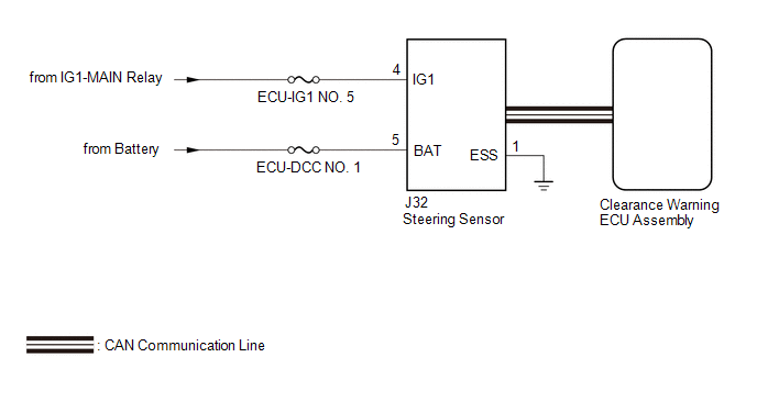
WIRING DIAGRAM
CAUTION / NOTICE / HINT
NOTICE:
-
After turning the engine switch off, waiting time may be required before disconnecting the cable from the negative (-) battery terminal. Therefore make sure to read the disconnecting the cable from the negative (-) battery terminal notices before proceeding with work.
Click here
.gif)
-
After replacing an ultrasonic sensor or the clearance warning ECU assembly, perform the necessary procedures (adjustment, calibration, initialization or registration).
Click here
- Inspect the fuses for circuits related to this system before performing the following procedure.
PROCEDURE
| 1. | CHECK HARNESS AND CONNECTOR (STEERING SENSOR POWER SOURCE) |
(a) Disconnect the J32 steering sensor connector.
(b) Measure the voltage according to the value(s) in the table below.
Standard Voltage:
| Tester Connection | Condition | Specified Condition |
|---|---|---|
| J32-4 (IG1) - J32-1 (ESS) | Engine switch on (IG) | 11 to 14 V |
| NG |  | REPAIR OR REPLACE HARNESS OR CONNECTOR |
|

| 2. | CHECK HARNESS AND CONNECTOR (STEERING SENSOR POWER SOURCE) |
(a) Measure the resistance according to the value(s) in the table below.
Standard Resistance:
| Tester Connection | Condition | Specified Condition |
|---|---|---|
| J32-1 (ESS) - Body ground | Always | Below 1 Ω |
(b) Measure the voltage according to the value(s) in the table below.
Standard Voltage:
| Tester Connection | Condition | Specified Condition |
|---|---|---|
| J32-5 (BAT) - J32-1 (ESS) | Always | 11 to 14 V |
| OK | | REPLACE STEERING SENSOR |
| NG | | REPAIR OR REPLACE HARNESS OR CONNECTOR |
 ECU Malfunction (C1611)
DESCRIPTION If the clearance warning ECU assembly detects an internal malfunction during self-diagnosis, DTC C1611 is stored. DTC No. Detection Item DTC Detection Condition Trouble Area C ...
 Steering Angle Sensor Failure (C1626)
DESCRIPTION This DTC is stored if the clearance warning ECU assembly receives a signal via CAN communication from the steering sensor that indicates an internal malfunction. DTC No. Detection Ite ...
Other materials:
Lexus RX (RX 350L, RX450h) 2016-2026 Repair Manual > Sfi System: Diagnosis System
DIAGNOSIS SYSTEM DESCRIPTION When troubleshooting OBD II (On-Board Diagnostics) vehicles, the Techstream (complying with SAE J1978) must be connected to the DLC3 (Data Link Connector 3) of the vehicle. Various data in the vehicle's ECM (Engine Control Module) can be then read. OBD II regulations re ...
Lexus RX (RX 350L, RX450h) 2016-2026 Repair Manual > Brake (front): Front Disc Brake Pad
ReplacementREPLACEMENT CAUTION / NOTICE / HINT NOTICE: After replacing the front disc brake pads, the brake pedal may feel soft due to clearance between the front disc brake pads and front disc. Depress the brake pedal several times until the brake pedal feels firm. HINT:
Use the same procedure f ...
Lexus RX (RX 350L, RX450h) 2016-{YEAR} Owners Manual
- For your information
- Pictorial index
- For safety and security
- Instrument cluster
- Operation of each component
- Driving
- Lexus Display Audio system
- Interior features
- Maintenance and care
- When trouble arises
- Vehicle specifications
- For owners
Lexus RX (RX 350L, RX450h) 2016-{YEAR} Repair Manual

0.0119