Lexus RX (RX 350L, RX450h) 2016-2026 Repair Manual: Terminals Of Ecu
TERMINALS OF ECU
CLEARANCE WARNING ECU ASSEMBLY
.png)
(a) Disconnect the J38 clearance warning ECU assembly connector.
(b) Measure the voltage and resistance on the wire harness side connector according to the value(s) in the table below.
| Terminal No. (Symbol) | Wiring Color | Terminal Description | Condition | Specified Condition |
|---|---|---|---|---|
| J38-1 (IG) - J38-30 (E) | SB - W-B | IG power source signal | Engine switch off | Below 1 V |
| Engine switch on (IG) | 11 to 14 V | |||
| J38-30 (E) - Body ground | W-B - Body ground | Ground | Always | Below 1 Ω |
(c) Reconnect the J38 clearance warning ECU assembly connector.
(d) Measure the voltage and resistance check for pulses according to the value(s) in the table below.
| Terminal No. (Symbol) | Wiring Color | Terminal Description | Condition | Specified Condition |
|---|---|---|---|---|
| *: for 12.3 Inch Display with Parking Assist Monitor System | ||||
| J38-4 (BOF) - J38-30 (E) | P - W-B | Power source for front sensor circuit | Engine switch off | Below 1 V |
| 11 to 14 V | |||
| J38-6 (E5) - J38-30 (E) | L - W-B | Ground for front clearance sonar | Always | Below 1 Ω |
| J38-8 (SOF) - J38-30 (E) | B - W-B | Front sensor communication signal (Front clearance sonar sensor) |
| Pulse generation (Refer to waveform 1) |
| J38-14 (CBZ) - J38-13 (EF) | Y - P | Clearance warning buzzer signal | Buzzer sounding | Pulse generation (Refer to waveform 2) |
| J38-15 (BBZ) - J38-16 (ER) | R - W | Clearance warning buzzer signal | Buzzer sounding | Pulse generation (Refer to waveform 2) |
| J38-22 (BOR) - J38-30 (E) | LG - W-B | Power source for rear sensor circuit | Engine switch off | Below 1 V |
| 11 to 14 V | |||
| J38-23 (E1) - J38-30 (E) | GR - W-B | Ground for rear clearance sonar | Always | Below 1 Ω |
| J38-24 (SOR) - J38-30 (E) | SB - W-B | Rear sensor communication signal (Rear clearance sonar sensor) |
| Pulse generation (Refer to waveform 1) |
| J38-28 (STP) - J38-30 (E)* | V - W-B | Reverse signal input |
| 11 to 14 V |
| Below 1 V | |||
| J38-31 (IND) - J38-30 (E)* | R - W-B | Reverse signal output |
| Below 3 V |
| 8 V or higher | |||
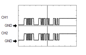
(e) Using an oscilloscope, check waveform 1.
(1) Waveform 1 (Reference)
| Item | Content |
|---|---|
| Measurement terminal |
|
| Measurement setting | 5 V/DIV., 1 ms./DIV. |
| Condition |
|
HINT:
The waveforms for CH1 and CH2 are same.
(f) Using an oscilloscope, check waveform 2.
(1) Waveform 2 (Reference)
.png)
| Item | Content |
|---|---|
| Measurement terminal | J38-14 (CBZ) - J38-13 (EF) J38-15 (BBZ) - J38-16 (ER) |
| Measurement setting | 2 V/DIV., 500 μs./DIV. |
| Condition | Buzzer sounding |
HINT:
The amplitude of the waveform changes according to the set volume.
 Problem Symptoms Table
PROBLEM SYMPTOMS TABLE HINT:
Use the table below to help determine the cause of problem symptoms. If multiple suspected areas are listed, the potential causes of the symptoms are listed in order of ...
 Diagnosis System
DIAGNOSIS SYSTEM DESCRIPTION (a) When troubleshooting a vehicle with a diagnosis system, the only difference from the usual troubleshooting procedure is connecting the Techstream to the vehicle and re ...
Other materials:
Lexus RX (RX 350L, RX450h) 2016-2026 Repair Manual > Fuel System: Precaution
PRECAUTION CAUTION:
The fuel tank assembly is very heavy. Be sure to follow the procedure described in the repair manual, or the fuel tank assembly may fall off the engine lifter.
To prevent serious injury due to fuel spray from the high-pressure fuel lines, always discharge fuel system pressu ...
Lexus RX (RX 350L, RX450h) 2016-2026 Repair Manual > Smart Access System With Push-button Start (for Start Function): Customize Parameters
CUSTOMIZE PARAMETERS CUSTOMIZE SMART ACCESS SYSTEM WITH PUSH-BUTTON START (for Start Function) NOTICE:
When the customer requests a change in a function, first make sure that the function can be customized.
Record the current settings before customizing.
HINT: The following items can be cust ...
Lexus RX (RX 350L, RX450h) 2016-{YEAR} Owners Manual
- For your information
- Pictorial index
- For safety and security
- Instrument cluster
- Operation of each component
- Driving
- Lexus Display Audio system
- Interior features
- Maintenance and care
- When trouble arises
- Vehicle specifications
- For owners
Lexus RX (RX 350L, RX450h) 2016-{YEAR} Repair Manual

0.0106