Lexus RX (RX 350L, RX450h) 2016-2026 Repair Manual: Rear Sensor Communication Malfunction (C1AED)
DESCRIPTION
This DTC is stored when there is an open or short circuit in the communication line between the rear sensors and the ECU, or when there is a malfunction in a rear sensor.
| DTC No. | Detection Item | DTC Detection Condition | Trouble Area |
|---|---|---|---|
| C1AED | Rear Sensor Communication Malfunction | An open or short circuit in the communication line between the rear sensors and ECU or a malfunction in a rear sensor during initialization mode after the engine switch is turned on (IG). |
|
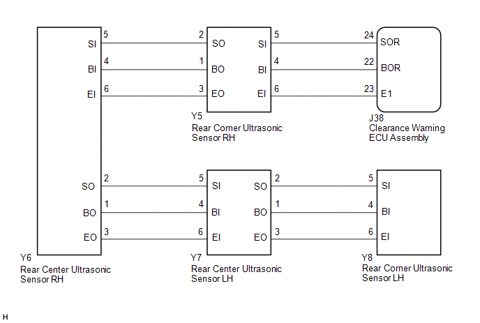
WIRING DIAGRAM
PROCEDURE
| 1. | INITIALIZE REAR CORNER ULTRASONIC SENSOR AND REAR CENTER ULTRASONIC SENSOR |
(a) Initialize the rear corner ultrasonic sensor and rear center ultrasonic sensor.
Click here .gif)
|

| 2. | CHECK DTC OUTPUT (C1AED) |
(a) Check for DTCs.
Body Electrical > Advanced Parking Guidance/ICS/Intuitive P/A > Trouble Codes(b) Clear the DTCs.
Body Electrical > Advanced Parking Guidance/ICS/Intuitive P/A > Clear DTCs(c) Recheck for DTCs.
Body Electrical > Advanced Parking Guidance/ICS/Intuitive P/A > Trouble Codes| Result | Proceed to |
|---|---|
| DTC C1AED is output | A |
| No DTCs are output | B |
| B |  | USE SIMULATION METHOD TO CHECK |
|
| 3. | CHECK HARNESS AND CONNECTOR (CLEARANCE WARNING ECU ASSEMBLY - REAR CORNER ULTRASONIC SENSOR RH) |
(a) Disconnect the J38 clearance warning ECU assembly connector.
(b) Disconnect the Y5 rear corner ultrasonic sensor RH connector.
(c) Measure the resistance according to the value(s) in the table below.
Standard Resistance:
| Tester Connection | Condition | Specified Condition |
|---|---|---|
| J38-22 (BOR) - Y5-4 (BI) | Always | Below 1 Ω |
| J38-24 (SOR) - Y5-5 (SI) | Always | Below 1 Ω |
| J38-23 (E1) - Y5-6 (EI) | Always | Below 1 Ω |
| J38-22 (BOR) or Y5-4 (BI) - Body ground | Always | 10 kΩ or higher |
| J38-24 (SOR) or Y5-5 (SI) - Body ground | Always | 10 kΩ or higher |
| J38-23 (E1) or Y5-6 (EI) - Body ground | Always | 10 kΩ or higher |
| NG | | REPAIR OR REPLACE HARNESS OR CONNECTOR |
|
| 4. | CHECK HARNESS AND CONNECTOR (REAR CORNER ULTRASONIC SENSOR RH - REAR CENTER ULTRASONIC SENSOR RH) |
(a) Disconnect the Y6 rear center ultrasonic sensor RH connector.
(b) Measure the resistance according to the value(s) in the table below.
Standard Resistance:
| Tester Connection | Condition | Specified Condition |
|---|---|---|
| Y5-1 (BO) - Y6-4 (BI) | Always | Below 1 Ω |
| Y5-2 (SO) - Y6-5 (SI) | Always | Below 1 Ω |
| Y5-3 (EO) - Y6-6 (EI) | Always | Below 1 Ω |
| Y5-1 (BO) or Y6-4 (BI) - Body ground | Always | 10 kΩ or higher |
| Y5-2 (SO) or Y6-5 (SI) - Body ground | Always | 10 kΩ or higher |
| Y5-3 (EO) or Y6-6 (EI) - Body ground | Always | 10 kΩ or higher |
| NG | | REPAIR OR REPLACE HARNESS OR CONNECTOR |
|
| 5. | CHECK HARNESS AND CONNECTOR (REAR CENTER ULTRASONIC SENSOR RH - REAR CENTER ULTRASONIC SENSOR LH) |
(a) Disconnect the Y7 rear center ultrasonic sensor LH connector.
(b) Measure the resistance according to the value(s) in the table below.
Standard Resistance:
| Tester Connection | Condition | Specified Condition |
|---|---|---|
| Y6-1 (BO) - Y7-4 (BI) | Always | Below 1 Ω |
| Y6-2 (SO) - Y7-5 (SI) | Always | Below 1 Ω |
| Y6-3 (EO) - Y7-6 (EI) | Always | Below 1 Ω |
| Y6-1 (BO) or Y7-4 (BI) - Body ground | Always | 10 kΩ or higher |
| Y6-2 (SO) or Y7-5 (SI) - Body ground | Always | 10 kΩ or higher |
| Y6-3 (EO) or Y7-6 (EI) - Body ground | Always | 10 kΩ or higher |
| NG | | REPAIR OR REPLACE HARNESS OR CONNECTOR |
|
| 6. | CHECK HARNESS AND CONNECTOR (REAR CENTER ULTRASONIC SENSOR LH - REAR CORNER ULTRASONIC SENSOR LH) |
(a) Disconnect the Y8 rear corner ultrasonic sensor LH connector.
(b) Measure the resistance according to the value(s) in the table below.
Standard Resistance:
| Tester Connection | Condition | Specified Condition |
|---|---|---|
| Y7-1 (BO) - Y8-4 (BI) | Always | Below 1 Ω |
| Y7-2 (SO) - Y8-5 (SI) | Always | Below 1 Ω |
| Y7-3 (EO) - Y8-6 (EI) | Always | Below 1 Ω |
| Y7-1 (BO) or Y8-4 (BI) - Body ground | Always | 10 kΩ or higher |
| Y7-2 (SO) or Y8-5 (SI) - Body ground | Always | 10 kΩ or higher |
| Y7-3 (EO) or Y8-6 (EI) - Body ground | Always | 10 kΩ or higher |
| NG | | REPAIR OR REPLACE HARNESS OR CONNECTOR |
|
| 7. | INSPECT REAR CORNER ULTRASONIC SENSOR RH |
| (a) Measure the resistance according to the value(s) in the table below. Standard Resistance:
|
|
| NG | | REPLACE REAR CORNER ULTRASONIC SENSOR RH |
|
| 8. | INSPECT REAR CENTER ULTRASONIC SENSOR RH |
| (a) Measure the resistance according to the value(s) in the table below. Standard Resistance:
|
|
| NG | | REPLACE REAR CENTER ULTRASONIC SENSOR RH |
|
| 9. | INSPECT REAR CENTER ULTRASONIC SENSOR LH |
| (a) Measure the resistance according to the value(s) in the table below. Standard Resistance:
|
|
| NG | | REPLACE REAR CENTER ULTRASONIC SENSOR LH |
|
| 10. | INSPECT REAR CORNER ULTRASONIC SENSOR LH |
| (a) Measure the resistance according to the value(s) in the table below. Standard Resistance:
|
|
| NG | | REPLACE REAR CORNER ULTRASONIC SENSOR LH |
|
| 11. | REPLACE REAR CORNER ULTRASONIC SENSOR RH |
Click here
|
| 12. | CHECK DTC OUTPUT (C1AED) |
(a) Clear the DTCs.
Body Electrical > Advanced Parking Guidance/ICS/Intuitive P/A > Clear DTCs(b) Check for DTCs.
Body Electrical > Advanced Parking Guidance/ICS/Intuitive P/A > Trouble Codes| Result | Proceed to |
|---|---|
| DTC C1AED is output | A |
| No DTCs are output | B |
| B | | END (REAR RIGHT SENSOR WAS DEFECTIVE) |
|
| 13. | REPLACE REAR CENTER ULTRASONIC SENSOR RH |
Click here
|
| 14. | CHECK DTC OUTPUT (C1AED) |
(a) Clear the DTCs.
Body Electrical > Advanced Parking Guidance/ICS/Intuitive P/A > Clear DTCs(b) Check for DTCs.
Body Electrical > Advanced Parking Guidance/ICS/Intuitive P/A > Trouble Codes| Result | Proceed to |
|---|---|
| DTC C1AED is output | A |
| No DTCs are output | B |
| B | | END (REAR RIGHT CENTER SENSOR WAS DEFECTIVE) |
|
| 15. | REPLACE REAR CENTER ULTRASONIC SENSOR LH |
Click here
|
| 16. | CHECK DTC OUTPUT (C1AED) |
(a) Clear the DTCs.
Body Electrical > Advanced Parking Guidance/ICS/Intuitive P/A > Clear DTCs(b) Check for DTCs.
Body Electrical > Advanced Parking Guidance/ICS/Intuitive P/A > Trouble Codes| Result | Proceed to |
|---|---|
| DTC C1AED is output | A |
| No DTCs are output | B |
| B | | END (REAR LEFT CENTER SENSOR WAS DEFECTIVE) |
|
| 17. | REPLACE REAR CORNER ULTRASONIC SENSOR LH |
Click here
|
| 18. | CHECK DTC OUTPUT (C1AED) |
(a) Clear the DTCs.
Body Electrical > Advanced Parking Guidance/ICS/Intuitive P/A > Clear DTCs(b) Check for DTCs.
Body Electrical > Advanced Parking Guidance/ICS/Intuitive P/A > Trouble Codes| Result | Proceed to |
|---|---|
| DTC C1AED is output | A |
| No DTCs are output | B |
| A | | REPLACE CLEARANCE WARNING ECU ASSEMBLY |
| B | | END (REAR LEFT SENSOR WAS DEFECTIVE) |
 Front Sensor Communication Malfunction (C1AEC)
DESCRIPTION This DTC is stored when there is an open or short circuit in the communication line between the front sensors and the ECU, or when there is a malfunction in a front sensor. DTC No. De ...
 Control Module Communication Bus "A" Off (U0073,U0155)
DESCRIPTION These DTCs are stored when the clearance warning ECU assembly cannot receive and recognize several signals via the CAN communication line. DTC No. Detection Item DTC Detection Condi ...
Other materials:
Lexus RX (RX 350L, RX450h) 2016-2026 Repair Manual > Front Camera System: Utility
UTILITY NOTICE:
If the forward recognition camera has been replaced with a new one or the windshield glass has been removed and installed, it is necessary to perform forward recognition camera adjustment. HINT: Forward recognition camera adjustment can be performed by using either One Time Recogn ...
Lexus RX (RX 350L, RX450h) 2016-2026 Repair Manual > Navigation System: GVIF Disconnected (from Extension Module to H/U) (B153A)
DESCRIPTION The radio receiver assembly and navigation ECU are connected via video signal (digital) lines. This DTC is stored when a video signal (digital) line is disconnected. DTC No. Detection Item DTC Detection Condition Trouble Area B153A GVIF Disconnected (from Extension Module ...
Lexus RX (RX 350L, RX450h) 2016-{YEAR} Owners Manual
- For your information
- Pictorial index
- For safety and security
- Instrument cluster
- Operation of each component
- Driving
- Lexus Display Audio system
- Interior features
- Maintenance and care
- When trouble arises
- Vehicle specifications
- For owners
Lexus RX (RX 350L, RX450h) 2016-{YEAR} Repair Manual

0.0174