Lexus RX (RX 350L, RX450h) 2016-2026 Repair Manual: Front Sensor Communication Malfunction (C1AEC)
DESCRIPTION
This DTC is stored when there is an open or short circuit in the communication line between the front sensors and the ECU, or when there is a malfunction in a front sensor.
| DTC No. | Detection Item | DTC Detection Condition | Trouble Area |
|---|---|---|---|
| C1AEC | Front Sensor Communication Malfunction | An open or short circuit in the communication line between the front sensors and ECU or a malfunction in a front sensor during initialization mode after the engine switch is turned on (IG). |
|
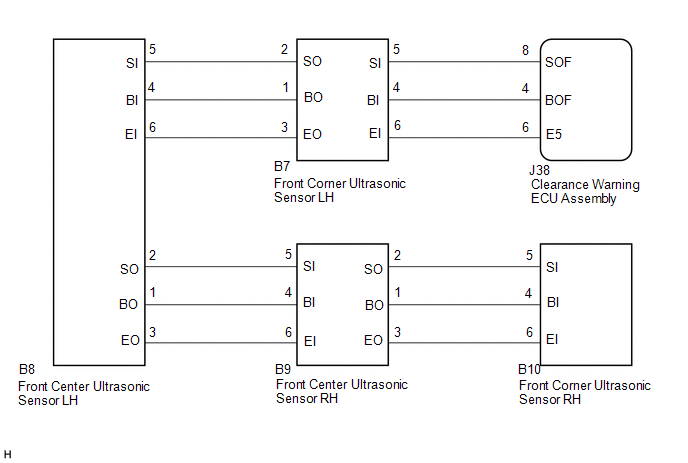
WIRING DIAGRAM
PROCEDURE
| 1. | INITIALIZE FRONT CENTER ULTRASONIC SENSOR AND FRONT CORNER ULTRASONIC SENSOR |
(a) Initialize the front center ultrasonic sensor and front corner ultrasonic sensor.
Click here .gif)
|

| 2. | CHECK DTC OUTPUT (C1AEC) |
(a) Check for DTCs.
Body Electrical > Advanced Parking Guidance/ICS/Intuitive P/A > Trouble Codes(b) Clear the DTCs.
Body Electrical > Advanced Parking Guidance/ICS/Intuitive P/A > Clear DTCs(c) Recheck for DTCs.
Body Electrical > Advanced Parking Guidance/ICS/Intuitive P/A > Trouble Codes| Result | Proceed to |
|---|---|
| DTC C1AEC is output | A |
| No DTCs are output | B |
| B |  | USE SIMULATION METHOD TO CHECK |
|
| 3. | CHECK HARNESS AND CONNECTOR (CLEARANCE WARNING ECU ASSEMBLY - FRONT CORNER ULTRASONIC SENSOR LH) |
(a) Disconnect the J38 clearance warning ECU assembly connector.
(b) Disconnect the B7 front corner ultrasonic sensor LH connector.
(c) Measure the resistance according to the value(s) in the table below.
Standard Resistance:
| Tester Connection | Condition | Specified Condition |
|---|---|---|
| J38-4 (BOF) - B7-4 (BI) | Always | Below 1 Ω |
| J38-8 (SOF) - B7-5 (SI) | Always | Below 1 Ω |
| J38-6 (E5) - B7-6 (EI) | Always | Below 1 Ω |
| J38-4 (BOF) or B7-4 (BI) - Body ground | Always | 10 kΩ or higher |
| J38-8 (SOF) or B7-5 (SI) - Body ground | Always | 10 kΩ or higher |
| J38-6 (E5) or B7-6 (EI) - Body ground | Always | 10 kΩ or higher |
| NG | | REPAIR OR REPLACE HARNESS OR CONNECTOR |
|
| 4. | CHECK HARNESS AND CONNECTOR (FRONT CORNER ULTRASONIC SENSOR LH - FRONT CENTER ULTRASONIC SENSOR LH) |
(a) Disconnect the B8 front center ultrasonic sensor LH connector.
(b) Measure the resistance according to the value(s) in the table below.
Standard Resistance:
| Tester Connection | Condition | Specified Condition |
|---|---|---|
| B7-1 (BO) - B8-4 (BI) | Always | Below 1 Ω |
| B7-2 (SO) - B8-5 (SI) | Always | Below 1 Ω |
| B7-3 (EO) - B8-6 (EI) | Always | Below 1 Ω |
| B7-1 (BO) or B8-4 (BI) - Body ground | Always | 10 kΩ or higher |
| B7-2 (SO) or B8-5 (SI) - Body ground | Always | 10 kΩ or higher |
| B7-3 (EO) or B8-6 (EI) - Body ground | Always | 10 kΩ or higher |
| NG | | REPAIR OR REPLACE HARNESS OR CONNECTOR |
|
| 5. | CHECK HARNESS AND CONNECTOR (FRONT CENTER ULTRASONIC SENSOR LH - FRONT CENTER ULTRASONIC SENSOR RH) |
(a) Disconnect the B9 front center ultrasonic sensor RH connector.
(b) Measure the resistance according to the value(s) in the table below.
Standard Resistance:
| Tester Connection | Condition | Specified Condition |
|---|---|---|
| B8-1 (BO) - B9-4 (BI) | Always | Below 1 Ω |
| B8-2 (SO) - B9-5 (SI) | Always | Below 1 Ω |
| B8-3 (EO) - B9-6 (EI) | Always | Below 1 Ω |
| B8-1 (BO) or B9-4 (BI) - Body ground | Always | 10 kΩ or higher |
| B8-2 (SO) or B9-5 (SI) - Body ground | Always | 10 kΩ or higher |
| B8-3 (EO) or B9-6 (EI) - Body ground | Always | 10 kΩ or higher |
| NG | | REPAIR OR REPLACE HARNESS OR CONNECTOR |
|
| 6. | CHECK HARNESS AND CONNECTOR (FRONT CENTER ULTRASONIC SENSOR RH - FRONT CORNER ULTRASONIC SENSOR RH) |
(a) Disconnect the B10 front corner ultrasonic sensor RH connector.
(b) Measure the resistance according to the value(s) in the table below.
Standard Resistance:
| Tester Connection | Condition | Specified Condition |
|---|---|---|
| B9-1 (BO) - B10-4 (BI) | Always | Below 1 Ω |
| B9-2 (SO) - B10-5 (SI) | Always | Below 1 Ω |
| B9-3 (EO) - B10-6 (EI) | Always | Below 1 Ω |
| B9-1 (BO) or B10-4 (BI) - Body ground | Always | 10 kΩ or higher |
| B9-2 (SO) or B10-5 (SI) - Body ground | Always | 10 kΩ or higher |
| B9-3 (EO) or B10-6 (EI) - Body ground | Always | 10 kΩ or higher |
| NG | | REPAIR OR REPLACE HARNESS OR CONNECTOR |
|
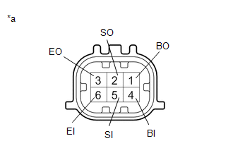
| 7. | INSPECT FRONT CORNER ULTRASONIC SENSOR LH |
| (a) Measure the resistance according to the value(s) in the table below. Standard Resistance:
|
|
| NG | | REPLACE FRONT CORNER ULTRASONIC SENSOR LH |
|
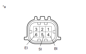
| 8. | INSPECT FRONT CENTER ULTRASONIC SENSOR LH |
| (a) Measure the resistance according to the value(s) in the table below. Standard Resistance:
|
|
| NG | | REPLACE FRONT CENTER ULTRASONIC SENSOR LH |
|
| 9. | INSPECT FRONT CENTER ULTRASONIC SENSOR RH |
| (a) Measure the resistance according to the value(s) in the table below. Standard Resistance:
|
|
| NG | | REPLACE FRONT CENTER ULTRASONIC SENSOR RH |
|
| 10. | INSPECT FRONT CORNER ULTRASONIC SENSOR RH |
| (a) Measure the resistance according to the value(s) in the table below. Standard Resistance:
|
|
| NG | | REPLACE FRONT CORNER ULTRASONIC SENSOR RH |
|
| 11. | REPLACE FRONT CORNER ULTRASONIC SENSOR LH |
Click here
|
| 12. | CHECK DTC OUTPUT (C1AEC) |
(a) Clear the DTCs.
Body Electrical > Advanced Parking Guidance/ICS/Intuitive P/A > Clear DTCs(b) Check for DTCs.
Body Electrical > Advanced Parking Guidance/ICS/Intuitive P/A > Trouble Codes| Result | Proceed to |
|---|---|
| DTC C1AEC is output | A |
| No DTCs are output | B |
| B | | END (FRONT LEFT SENSOR WAS DEFECTIVE) |
|
| 13. | REPLACE FRONT CENTER ULTRASONIC SENSOR LH |
Click here
|
| 14. | CHECK DTC OUTPUT (C1AEC) |
(a) Clear the DTCs.
Body Electrical > Advanced Parking Guidance/ICS/Intuitive P/A > Clear DTCs(b) Check for DTCs.
Body Electrical > Advanced Parking Guidance/ICS/Intuitive P/A > Trouble Codes| Result | Proceed to |
|---|---|
| DTC C1AEC is output | A |
| No DTCs are output | B |
| B | | END (FRONT LEFT CENTER SENSOR WAS DEFECTIVE) |
|
| 15. | REPLACE FRONT CENTER ULTRASONIC SENSOR RH |
Click here
|
| 16. | CHECK DTC OUTPUT (C1AEC) |
(a) Clear the DTCs.
Body Electrical > Advanced Parking Guidance/ICS/Intuitive P/A > Clear DTCs(b) Check for DTCs.
Body Electrical > Advanced Parking Guidance/ICS/Intuitive P/A > Trouble Codes| Result | Proceed to |
|---|---|
| DTC C1AEC is output | A |
| No DTCs are output | B |
| B | | END (FRONT RIGHT CENTER SENSOR WAS DEFECTIVE) |
|
| 17. | REPLACE FRONT CORNER ULTRASONIC SENSOR RH |
Click here
|
| 18. | CHECK DTC OUTPUT (C1AEC) |
(a) Clear the DTCs.
Body Electrical > Advanced Parking Guidance/ICS/Intuitive P/A > Clear DTCs(b) Check for DTCs.
Body Electrical > Advanced Parking Guidance/ICS/Intuitive P/A > Trouble Codes| Result | Proceed to |
|---|---|
| DTC C1AEC is output | A |
| No DTCs are output | B |
| A | | REPLACE CLEARANCE WARNING ECU ASSEMBLY |
| B | | END (FRONT RIGHT SENSOR WAS DEFECTIVE) |
 Rear Right Sensor Malfunction (C1AE9)
DESCRIPTION The rear corner ultrasonic sensor RH is installed to the rear bumper. The clearance warning ECU assembly detects obstacles based on signals received from the rear corner ultrasonic sensor ...
 Rear Sensor Communication Malfunction (C1AED)
DESCRIPTION This DTC is stored when there is an open or short circuit in the communication line between the rear sensors and the ECU, or when there is a malfunction in a rear sensor. DTC No. Dete ...
Other materials:
Lexus RX (RX 350L, RX450h) 2016-2026 Repair Manual > Navigation System: Radio Receiver Power Source Circuit
DESCRIPTION This is the power source circuit to operate the radio receiver assembly. WIRING DIAGRAM CAUTION / NOTICE / HINT NOTICE: Inspect the fuses for circuits related to this system before performing the following procedure. PROCEDURE 1. CHECK HARNESS AND CONNECTOR (RADIO RECEIVER ASSEMBL ...
Lexus RX (RX 350L, RX450h) 2016-2026 Repair Manual > Navigation System: Stereo Component Amplifier Disconnected (B15D3)
DESCRIPTION The radio receiver assembly and stereo component amplifier assembly are connected via MOST communication lines. When a MOST communication error occurs between the radio receiver assembly and stereo component amplifier assembly, this DTC will be stored. DTC No. Detection Item DTC D ...
Lexus RX (RX 350L, RX450h) 2016-{YEAR} Owners Manual
- For your information
- Pictorial index
- For safety and security
- Instrument cluster
- Operation of each component
- Driving
- Lexus Display Audio system
- Interior features
- Maintenance and care
- When trouble arises
- Vehicle specifications
- For owners
Lexus RX (RX 350L, RX450h) 2016-{YEAR} Repair Manual

0.0104