Lexus RX (RX 350L, RX450h) 2016-2026 Repair Manual: Removal
REMOVAL
CAUTION / NOTICE / HINT
The necessary procedures (adjustment, calibration, initialization, or registration) that must be performed after parts are removed and installed, or replaced during parking assist ECU removal/installation are shown below.
Necessary Procedures After Parts Removed/Installed/Replaced| Replaced Part or Performed Procedure | Necessary Procedure | Effect/Inoperative Function when Necessary Procedure not Performed | Link |
|---|---|---|---|
| Disconnect cable from negative battery terminal | Memorize steering angle neutral point | Lane Control System | |
| Pre-collision System | |||
| Intelligent Clearance Sonar System*1 | |||
| Parking Assist Monitor System | | ||
| Panoramic View Monitor System | | ||
| Lighting System (w/ Automatic Headlight Beam Level Control System) | | ||
| Initialize back door lock | Power Door Lock Control System | | |
| Reset back door close position | Power Back Door System (w/ Outside Door Control Switch) | | |
| Replacement of parking assist ECU |
| Panoramic view monitor system | |
*1: When performing learning using the Techstream.
Click here .gif)
PROCEDURE
1. PRECAUTION
NOTICE:
After turning the engine switch off, waiting time may be required before disconnecting the cable from the negative (-) battery terminal. Therefore, make sure to read the disconnecting the cable from the negative (-) battery terminal notices before proceeding with work.
Click here
2. DISCONNECT CABLE FROM NEGATIVE BATTERY TERMINAL
NOTICE:
When disconnecting the cable, some systems need to be initialized after the cable is reconnected.
Click here
3. REMOVE LOWER NO. 1 INSTRUMENT PANEL FINISH PANEL
Click here
4. REMOVE INSTRUMENT PANEL GARNISH RH
Click here
5. REMOVE FRONT DOOR SCUFF PLATE RH
HINT:
Use the same procedure as for the LH side.
Click here
6. REMOVE COWL SIDE TRIM BOARD RH
HINT:
Use the same procedure as for the LH side.
Click here
7. REMOVE NO. 2 INSTRUMENT PANEL UNDER COVER SUB-ASSEMBLY
Click here
8. REMOVE GLOVE COMPARTMENT DOOR ASSEMBLY
Click here
9. REMOVE PARKING ASSIST ECU
(a) Disconnect each connector.
(b) Remove the bolt and nut and parking assist ECU.
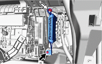
.png) | Bolt |
.png) | Nut |
 Components
COMPONENTS ILLUSTRATION *1 COWL SIDE TRIM BOARD RH *2 FRONT DOOR SCUFF PLATE RH *3 GLOVE COMPARTMENT DOOR ASSEMBLY *4 INSTRUMENT PANEL GARNISH RH *5 LOWER NO. 1 INSTRUMENT PA ...
 Installation
INSTALLATION PROCEDURE 1. INSTALL PARKING ASSIST ECU (a) Install the parking assist ECU with the bolt and nut. (b) Connect each connector. 2. INSTALL GLOVE COMPARTMENT DOOR ASSEMBLY Click here 3. IN ...
Other materials:
Lexus RX (RX 350L, RX450h) 2016-2026 Repair Manual > Electric Parking Brake System: Problem Symptoms Table
PROBLEM SYMPTOMS TABLE HINT:
Use the table below to help determine the cause of problem symptoms. If multiple suspected areas are listed, the potential causes of the symptoms are listed in order of probability in the "Suspected Area" column of the table. Check each symptom by checking the suspect ...
Lexus RX (RX 350L, RX450h) 2016-2026 Repair Manual > Meter / Gauge System: Lost Communication with EMV (B1321)
DESCRIPTION After the combination meter assembly has started, the combination meter assembly attempts to detect the radio receiver assembly by performing communication via local bus. This DTC is stored when the radio receiver assembly has been detected but communication between the combination meter ...
Lexus RX (RX 350L, RX450h) 2016-{YEAR} Owners Manual
- For your information
- Pictorial index
- For safety and security
- Instrument cluster
- Operation of each component
- Driving
- Lexus Display Audio system
- Interior features
- Maintenance and care
- When trouble arises
- Vehicle specifications
- For owners
Lexus RX (RX 350L, RX450h) 2016-{YEAR} Repair Manual

0.0094