Lexus RX (RX 350L, RX450h) 2016-2026 Repair Manual: Installation
INSTALLATION
PROCEDURE
1. INSTALL FRONT CORNER ULTRASONIC SENSOR RETAINER
HINT:
- Perform this procedure only when replacement of the front corner ultrasonic sensor retainer is necessary.
- If a front corner ultrasonic sensor retainer has been removed, replace it with a new one. Install the front corner ultrasonic sensor with a new front corner ultrasonic sensor retainer as a set to the front bumper assembly.
- The illustration is for the LH side. The orientation for the RH side is the opposite of the LH side.
| (a) Engage the 2 claws to install a new front corner ultrasonic sensor retainer to the front corner ultrasonic sensor. |
|
(b) Clean the surface of the front bumper assembly.
(1) Remove any remaining double-sided tape from the front bumper assembly.
(2) Wipe off any adhesive residue with cleaner.
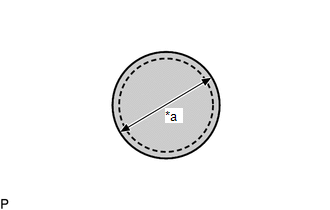
| (c) Cover the sensor installation hole with a 19 mm (0.748 in.) circular piece of tape. |
|
(d) Using a brush or felt, apply primer or equivalent to the front corner ultrasonic sensor retainer installation area.
NOTICE:
- Use a clean brush or felt.
- Do not touch the front bumper assembly until the primer has dried.
.png) | Primer |
(e) Confirm that the primer has completely dried by touching the front bumper assembly. Then remove the tape.
(f) Peel off the release paper from the front corner ultrasonic sensor retainer.
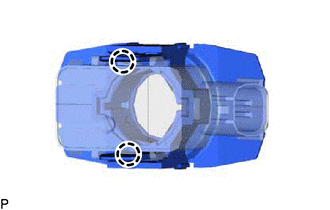
(g) Align the front corner ultrasonic sensor retainer with front corner ultrasonic sensor with the mark on the front bumper assembly and install it as shown in the illustration.
NOTICE:
- Ensure that the sensor tip is correctly inserted into the sensor installation hole of the front bumper assembly.
- Ensure that the front corner ultrasonic sensor retainer is within the scribed line.
- The double-sided tape of a front corner ultrasonic sensor retainer will deteriorate if it is detached. Make sure to replace the front corner ultrasonic sensor retainer with a new one when reattachment is necessary.
HINT:
Press the area shown in the illustration with a force of 30 N (3.0 kgf) for 3 seconds to securely install the front corner ultrasonic sensor retainer to the front bumper assembly. Confirm there is no clearance between the front corner ultrasonic sensor retainer and front bumper assembly.
| *a | Scribed Line |
.png) | Press Here |
2. INSTALL FRONT CORNER ULTRASONIC SENSOR
HINT:
The illustration is for the LH side. The orientation for the RH side is the opposite of the LH side.
(a) When replacing only the front corner ultrasonic sensor:
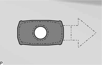
(1) Engage the 2 claws to install the front corner ultrasonic sensor as shown in the illustration.
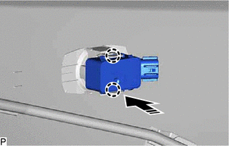
.png) | Install in this Direction |
(2) Connect the connector.
3. INSTALL FRONT CENTER ULTRASONIC SENSOR
HINT:
The illustration is for the LH side. The orientation for the RH side is the opposite of the LH side.
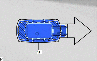
(a) Engage the 2 claws to install the front center ultrasonic sensor as shown in the illustration.
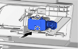
| | Install in this Direction |
(b) Connect the connector.
4. INSTALL FRONT BUMPER ASSEMBLY
Click here .gif)
5. PERFORM CALIBRATION
Click here
SST: 09989-00020
 Inspection
INSPECTION PROCEDURE 1. INSPECT FRONT CENTER ULTRASONIC SENSOR (a) Measure the resistance according to the value(s) in the table below. Standard Resistance: Tester Connection Condition Spec ...

Other materials:
Lexus RX (RX 350L, RX450h) 2016-2026 Repair Manual > Vacuum Switching Valve (for Acis): Removal
REMOVAL PROCEDURE 1. REMOVE V-BANK COVER SUB-ASSEMBLY Click here 2. REMOVE NO. 1 VACUUM SWITCHING VALVE ASSEMBLY (for ACIS) (a) Disconnect the No. 1 vacuum switching valve assembly (for ACIS) connector. (b) Disconnect the 2 vacuum hose assemblies from the No. 1 vacuum switching v ...
Lexus RX (RX 350L, RX450h) 2016-2026 Repair Manual > Smart Access System With Push-button Start (for Entry Function): Open in Front Floor Electrical Key Oscillator Circuit (B27A5)
DESCRIPTION The certification ECU (smart key ECU assembly) generates a request signal and transmits the signal to the No. 1 indoor electrical key antenna assembly (front floor). For the No. 1 indoor electrical key antenna assembly (front floor) to detect when the electrical key transmitter sub-assem ...
Lexus RX (RX 350L, RX450h) 2016-{YEAR} Owners Manual
- For your information
- Pictorial index
- For safety and security
- Instrument cluster
- Operation of each component
- Driving
- Lexus Display Audio system
- Interior features
- Maintenance and care
- When trouble arises
- Vehicle specifications
- For owners
Lexus RX (RX 350L, RX450h) 2016-{YEAR} Repair Manual

0.01