Lexus RX (RX 350L, RX450h) 2016-2026 Repair Manual: Remote Engine Starter does not Operate
WIRING DIAGRAM
CAUTION / NOTICE / HINT
NOTICE:
Before replacing the DCM (telematics transceiver), refer to Registration.
Click here .gif)
PROCEDURE
| 1. | CHECK SMART ACCESS SYSTEM WITH PUSH-BUTTON START (for Start Function) |
(a) Check that the engine can be started by pressing the engine switch.
| Result | Proceed to |
|---|---|
| Engine can be started. | A |
| Engine cannot be started. | B |
| B | .gif) | GO TO SMART ACCESS SYSTEM WITH PUSH-BUTTON START (for Start Function) |
|
.gif)
| 2. | REGISTRATION |
HINT:
If registration is not performed after replacing any of the following parts, the remote engine start and stop will not be available.- Certification ECU (smart key ECU assembly)
- DCM (telematics transceiver)
(a) Perform remote engine start and stop registration.
Click here
(b) Check if the problem symptom recurs.
| Result | Proceed to |
|---|---|
| System does not return to normal. | A |
| System returns to normal. | B |
| B | | END |
|
| 3. | CHECK DTC |
(a) Clear the DTCs.
Body Electrical > Smart Access > Clear DTCs(b) Check for DTCs.
Body Electrical > Smart Access > Trouble Codes| Result | Proceed to |
|---|---|
| DTC B2285 is not output. | A |
| DTC B2285 is output. | B |
| B | | GO TO DTC B2285 |
|
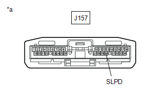
| 4. | CHECK DCM (TELEMATICS TRANSCEIVER) |
| (a) Disconnect the DCM (telematics transceiver) connector. |
|
(b) Measure the voltage according to the value(s) in the table below.
Standard Voltage:
| Tester Connection | Condition | Specified Condition |
|---|---|---|
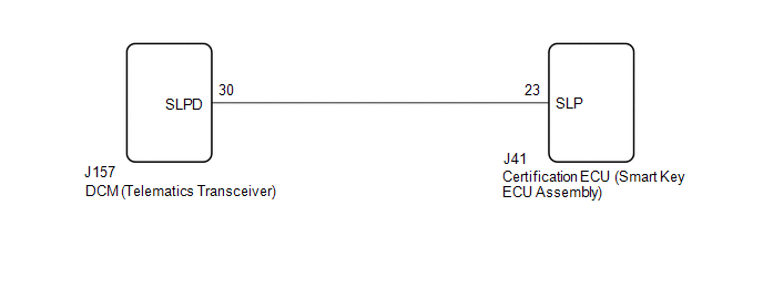
| J157-30 (SLPD) - Body ground | Steering locked | 11 to 14 V |
| Steering unlocked | Below 1.5 V |
HINT:
The steering locks when any door is opened with the shift lever in P and the engine switch off. The steering unlocks when the engine switch is turned on (ACC).
| OK | | REPLACE DCM (TELEMATICS TRANSCEIVER) |
|
| 5. | CHECK HARNESS AND CONNECTOR (DCM [TELEMATICS TRANSCEIVER] - CERTIFICATION ECU [SMART KEY ECU ASSEMBLY]) |
(a) Disconnect the J157 DCM (telematics transceiver) connector.
(b) Disconnect the J41 certification ECU (smart key ECU assembly) connector.
(c) Measure the resistance according to the value(s) in the table below.
Standard Resistance:
| Tester Connection | Condition | Specified Condition |
|---|---|---|
| J157-30 (SLPD) - J41-23 (SLP) | Always | Below 1 Ω |
| OK | | REPLACE CERTIFICATION ECU (SMART KEY ECU ASSEMBLY) |
| NG | | REPAIR OR REPLACE HARNESS OR CONNECTOR |
 Lost Communication with Body Control Module Missing Message (U014087,U015587,U016387)
DESCRIPTION These DTCs are stored when a malfunction occurs in the CAN communication circuit. DTC No. Detection Item DTC Detection Condition Trouble Area U014087 Lost Communication with ...
 Warning Notification Function Malfunction
PROCEDURE 1. CHECK PROBLEM SYMPTOM (WARNING NOTIFICATION FUNCTION) (a) Check the problem symptom. (1) Check the problem symptom of the warning notification function. Result Proceed to ...
Other materials:
Lexus RX (RX 350L, RX450h) 2016-2026 Repair Manual > Ambient Light (for Instrument Panel): Inspection
INSPECTION PROCEDURE 1. INSPECT INTERIOR ILLUMINATION LIGHT SUB-ASSEMBLY (INSTRUMENT PANEL AMBIENT ILLUMINATION LIGHT) (a) Apply battery voltage to the connector and check that the instrument panel ambient illumination light comes on. OK: Measurement Condition Condition Specified Conditio ...
Lexus RX (RX 350L, RX450h) 2016-2026 Repair Manual > Power Tilt And Power Telescopic Steering Column System: Terminals Of Ecu
TERMINALS OF ECU MULTIPLEX TILT AND TELESCOPIC ECU *a Component without harness connected (Multiplex Tilt and Telescopic ECU) - - (a) Measure the voltage and resistance according to the value(s) in the table below. Terminal No. (Symbol) Wiring Color Terminal Description Conditi ...
Lexus RX (RX 350L, RX450h) 2016-{YEAR} Owners Manual
- For your information
- Pictorial index
- For safety and security
- Instrument cluster
- Operation of each component
- Driving
- Lexus Display Audio system
- Interior features
- Maintenance and care
- When trouble arises
- Vehicle specifications
- For owners
Lexus RX (RX 350L, RX450h) 2016-{YEAR} Repair Manual

0.118