Lexus RX (RX 350L, RX450h) 2016-2026 Repair Manual: System Diagram
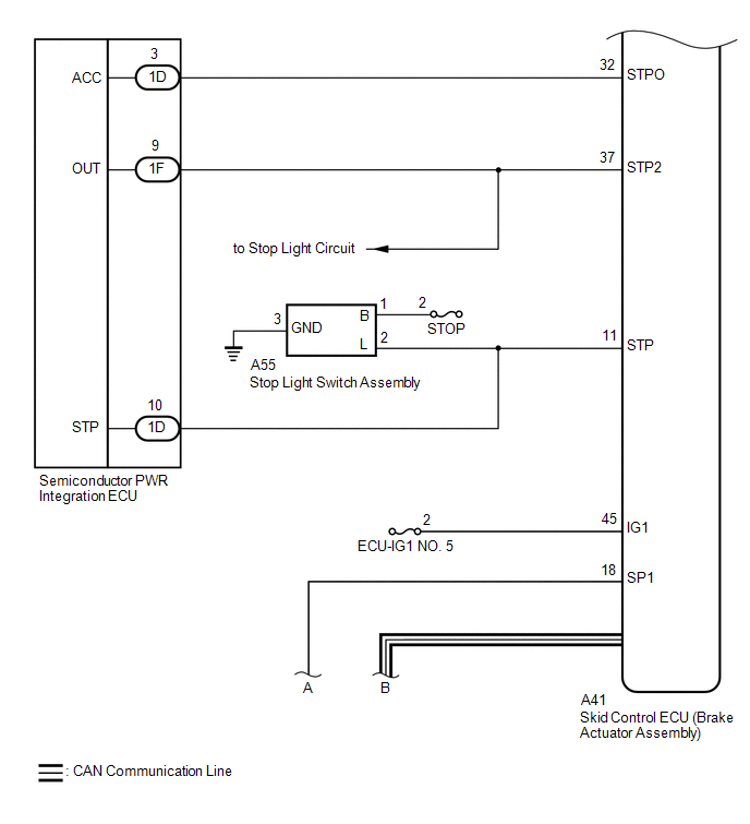
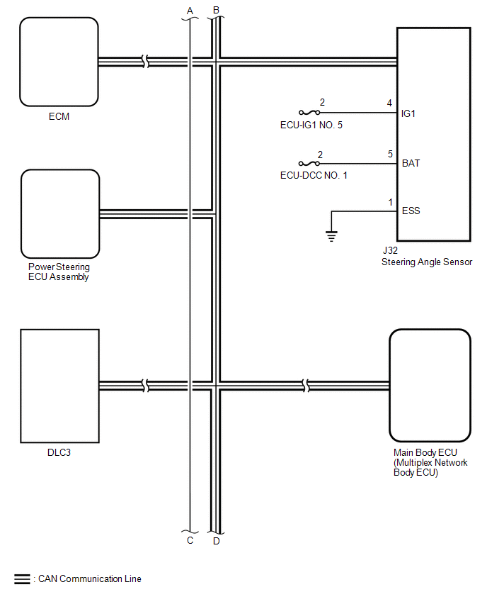
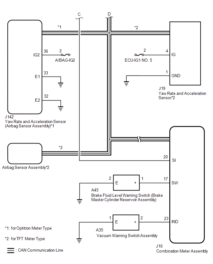
SYSTEM DIAGRAM
| Transmitting ECU (Transmitter) | Receiving ECU | Signal | Communication Method |
|---|---|---|---|
| Skid control ECU (Brake actuator assembly) | Steering angle sensor | Steering angle sensor request signal | CAN communication system |
| Steering angle sensor | Skid control ECU (Brake actuator assembly) | Steering angle sensor signal | CAN communication system |
| Skid control ECU (Brake actuator assembly) |
| Yaw rate and acceleration request signal | CAN communication system |
| Skid control ECU (Brake actuator assembly) | Yaw rate and acceleration signal | CAN communication system |
| Skid control ECU (Brake actuator assembly) | ECM |
| CAN communication system |
| ECM | Skid control ECU (Brake actuator assembly) |
| CAN communication system |
| Skid control ECU (brake actuator assembly) | Power steering ECU assembly |
| CAN communication system |
| Power steering ECU assembly | Skid control ECU (Brake actuator assembly) | Power steering system data signal | CAN communication system |
| Main body ECU (multiplex network body ECU) | Skid control ECU (Brake actuator assembly) |
| CAN communication system |
| Skid control ECU (Brake actuator assembly) | Combination meter assembly |
| CAN communication system |
| Airbag sensor assembly | Skid control ECU (Brake actuator assembly) | Secondary collision brake request signal | CAN communication system |
*1: for Optitron Meter Type
*2: for TFT Meter Type
 Parts Location
PARTS LOCATION ILLUSTRATION *A w/o AVS *B for 2WD *C for AWD - - *1 FRONT SPEED SENSOR RH *2 FRONT SPEED SENSOR LH *3 FRONT AXLE HUB SUB-ASSEMBLY RH - FRONT SPEED S ...
 How To Proceed With Troubleshooting
CAUTION / NOTICE / HINT HINT: *: Use the Techstream. PROCEDURE 1. VEHICLE BROUGHT TO WORKSHOP
NEXT 2. CUSTOMER PROBLEM ANALYSIS (a) Interview the customer and confir ...
Other materials:
Lexus RX (RX 350L, RX450h) 2016-2026 Repair Manual > Lighting System (w/o Automatic Headlight Beam Level Control System): Taillight Relay Circuit
DESCRIPTION The main body ECU (multiplex network body ECU) controls the operation of the TAIL relay. WIRING DIAGRAM CAUTION / NOTICE / HINT NOTICE:
Inspect the fuses for circuits related to this system before performing the following procedure.
Before replacing the main body ECU (multiplex net ...
Lexus RX (RX 350L, RX450h) 2016-2026 Repair Manual > Lighting System: Problem Symptoms Table
PROBLEM SYMPTOMS TABLE NOTICE: Before replacing the main ECU (multiplex network body ECU), refer to Service Bulletin. HINT: Use the table below to help determine the cause of problem symptoms. If multiple suspected areas are listed, the potential causes of the symptoms are listed in order of probabi ...
Lexus RX (RX 350L, RX450h) 2016-{YEAR} Owners Manual
- For your information
- Pictorial index
- For safety and security
- Instrument cluster
- Operation of each component
- Driving
- Lexus Display Audio system
- Interior features
- Maintenance and care
- When trouble arises
- Vehicle specifications
- For owners
Lexus RX (RX 350L, RX450h) 2016-{YEAR} Repair Manual

0.0119