Lexus RX (RX 350L, RX450h) 2016-2026 Repair Manual: Right Front Wheel Speed Sensor Circuit Short to Battery (C050612)
DESCRIPTION
Refer to DTC C05061F.
Click here .gif)
| DTC No. | Detection Item | DTC Detection Condition | Trouble Area |
|---|---|---|---|
| C050612 | Right Front Wheel Speed Sensor Circuit Short to Battery | The speed sensor short signal is ON continuously for 0.5 seconds or more. |
|
*: w/ AVS
WIRING DIAGRAM
Click here
CAUTION / NOTICE / HINT
NOTICE:
-
After replacing the skid control ECU (brake actuator assembly), perform "Calibration".
Click here
-
After replacing or removing and installing a speed sensor, perform Dealer Mode (Signal Check) inspection to confirm that the speed sensors are operating correctly.
Click here
PROCEDURE
| 1. | CHECK VEHICLE SPECIFICATION |
(a) Check the vehicle specification.
| Result | Proceed to |
|---|---|
| w/o AVS | A |
| w/ AVS | B |
| B | .gif) | GO TO STEP 5 |
|
.gif)
| 2. | CHECK HARNESS AND CONNECTOR (SENSOR GROUND CIRCUIT) |
| (a) Make sure that there is no looseness at the locking part and the connecting part of the connectors. OK: The connector is securely connected. |
|
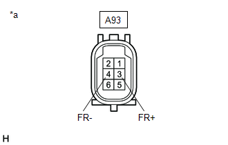
(b) Disconnect the A93 front speed sensor RH connector.
(c) Check both the connector case and the terminals for deformation and corrosion.
OK:
No deformation or corrosion.
(d) Turn the engine switch on (IG).
(e) Measure the voltage according to the value(s) in the table below.
Standard Voltage:
| Tester Connection | Condition | Specified Condition |
|---|---|---|
| A93-3 (FR+) - A93-4 (FR-) | Engine switch on (IG) | 11 to 14 V |
| OK | | REPLACE FRONT SPEED SENSOR RH |
|
| 3. | CHECK HARNESS AND CONNECTOR (SENSOR GROUND CIRCUIT) |
| (a) Turn the engine switch off. |
|

(b) Make sure that there is no looseness at the locking part and the connecting part of the connectors.
OK:
The connector is securely connected.
(c) Disconnect the A41 skid control ECU (brake actuator assembly) connector.
(d) Check both the connector case and the terminals for deformation and corrosion.
OK:
No deformation or corrosion.
(e) Measure the voltage according to the value(s) in the table below.
Standard Voltage:
| Tester Connection | Condition | Specified Condition |
|---|---|---|
| A93-4 (FR-) - Body ground | Always | Below 1.5 V |
| NG | | REPAIR OR REPLACE HARNESS OR CONNECTOR |
|
| 4. | CHECK HARNESS AND CONNECTOR (FRONT SPEED SENSOR RH - BRAKE ACTUATOR ASSEMBLY) |
(a) Measure the resistance according to the value(s) in the table below.
Standard Resistance:
| Tester Connection | Condition | Specified Condition |
|---|---|---|
| A93-3 (FR+) or A41-7 (FR+) - A93-4 (FR-) or A41-6 (FR-) | Always | 10 kΩ or higher |
| OK | | REPLACE BRAKE ACTUATOR ASSEMBLY |
| NG | | REPAIR OR REPLACE HARNESS OR CONNECTOR |
| 5. | CHECK HARNESS AND CONNECTOR (SENSOR GROUND CIRCUIT) |
| (a) Make sure that there is no looseness at the locking part and the connecting part of the connectors. OK: The connector is securely connected. |
|
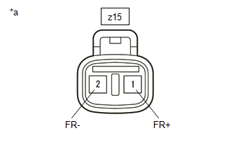
(b) Disconnect the z15 front speed sensor RH connector.
(c) Check both the connector case and the terminals for deformation and corrosion.
OK:
No deformation or corrosion.
(d) Turn the engine switch on (IG).
(e) Measure the voltage according to the value(s) in the table below.
Standard Voltage:
| Tester Connection | Condition | Specified Condition |
|---|---|---|
| z15-1 (FR+) - z15-2 (FR-) | Engine switch on (IG) | 11 to 14 V |
| OK | | REPLACE FRONT SPEED SENSOR RH |
|
| 6. | CHECK HARNESS AND CONNECTOR (SENSOR GROUND CIRCUIT) |
| (a) Turn the engine switch off. |
|

(b) Make sure that there is no looseness at the locking part and the connecting part of the connectors.
OK:
The connector is securely connected.
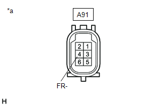
(c) Disconnect the A91 front skid control sensor wire RH connector.
(d) Check both the connector case and the terminals for deformation and corrosion.
OK:
No deformation or corrosion.
(e) Turn the engine switch on (IG).
(f) Measure the voltage according to the value(s) in the table below.
Standard Voltage:
| Tester Connection | Condition | Specified Condition |
|---|---|---|
| A91-3 (FR+) - A91-4 (FR-) | Engine switch on (IG) | 11 to 14 V |
| OK | | REPLACE FRONT SKID CONTROL SENSOR WIRE RH |
|
| 7. | CHECK HARNESS AND CONNECTOR (SENSOR GROUND CIRCUIT) |
| (a) Turn the engine switch off. |
|
(b) Make sure that there is no looseness at the locking part and the connecting part of the connectors.
OK:
The connector is securely connected.
(c) Disconnect the A41 skid control ECU (brake actuator assembly) connector.
(d) Check both the connector case and the terminals for deformation and corrosion.
OK:
No deformation or corrosion.
(e) Measure the voltage according to the value(s) in the table below.
Standard Voltage:
| Tester Connection | Condition | Specified Condition |
|---|---|---|
| A91-4 (FR-) - Body ground | Always | Below 1.5 V |
| NG | | REPAIR OR REPLACE HARNESS OR CONNECTOR |
|
| 8. | CHECK HARNESS AND CONNECTOR (FRONT SKID CONTROL SENSOR WIRE RH - BRAKE ACTUATOR ASSEMBLY) |
(a) Measure the resistance according to the value(s) in the table below.
Standard Resistance:
| Tester Connection | Condition | Specified Condition |
|---|---|---|
| A91-3 (FR+) or A41-7 (FR+) - A91-4 (FR-) or A41-6 (FR-) | Always | 10 kΩ or higher |
| OK | | REPLACE BRAKE ACTUATOR ASSEMBLY |
| NG | | REPAIR OR REPLACE HARNESS OR CONNECTOR |
 Left Front Wheel Speed Sensor Signal Has Too Many Pulses (C05003A,C05063A)
DESCRIPTION Refer to DTC C05001F. Click here DTC No. Detection Item DTC Detection Condition Trouble Area C05003A Left Front Wheel Speed Sensor Signal Has Too Many Pulses When not in ...
 Right Front Wheel Speed Sensor Circuit Short to Ground or Open (C050614)
DESCRIPTION Refer to DTC C05061F. Click here DTC No. Detection Item DTC Detection Condition Trouble Area C050614 Right Front Wheel Speed Sensor Circuit Short to Ground or Open An op ...
Other materials:
Lexus RX (RX 350L, RX450h) 2016-2026 Owners Manual > Driving procedures: EV drive mode
In EV drive mode, electric power is supplied by the hybrid battery
(traction
battery), and only the electric motor (traction motor) is used to drive the
vehicle.
This mode allows you to drive in residential areas early in the morning and late
at night, or in indoor parking lots, etc., witho ...
Lexus RX (RX 350L, RX450h) 2016-2026 Repair Manual > Windshield Outside Moulding: Components
COMPONENTS ILLUSTRATION *1 NO. 1 WINDSHIELD OUTSIDE MOULDING CLIP *2 NO. 3 WINDSHIELD OUTSIDE MOULDING CLIP *3 WINDSHIELD OUTSIDE MOULDING *4 WINDSHIELD GLASS ASSEMBLY ● Non-reusable part - - ...
Lexus RX (RX 350L, RX450h) 2016-{YEAR} Owners Manual
- For your information
- Pictorial index
- For safety and security
- Instrument cluster
- Operation of each component
- Driving
- Lexus Display Audio system
- Interior features
- Maintenance and care
- When trouble arises
- Vehicle specifications
- For owners
Lexus RX (RX 350L, RX450h) 2016-{YEAR} Repair Manual

0.0107