Lexus RX (RX 350L, RX450h) 2016-2026 Repair Manual: Brake Warning Light Remains ON
DESCRIPTION
This procedure is for troubleshooting when the brake warning light remains on but no DTCs are output.
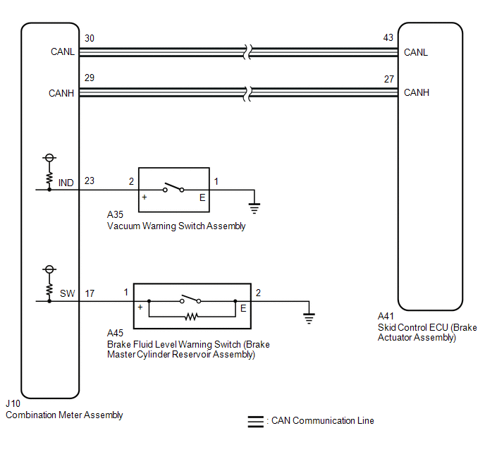
The skid control ECU (brake actuator assembly) controls the brake warning light in the combination meter assembly via CAN communication.
WIRING DIAGRAM
CAUTION / NOTICE / HINT
NOTICE:
-
After replacing the skid control ECU (brake actuator assembly), perform "Calibration".
Click here
.gif)
- Before performing this procedure, depress the brake pedal and confirm that the stop lights illuminate.
PROCEDURE
| 1. | PRE-CHECK |
(a) Check that all of the following conditions required for the brake warning light to turn off are met:
(1) The ABS warning light are not illuminated.
HINT:
If the ABS warning light remains illuminated, make sure that the conditions required for the ABS warning light to turn off are met.
Click here
(2) The brake fluid level in the brake master cylinder reservoir assembly is not low.
(3) The vacuum inside the brake booster decreases.
HINT:
When the vacuum inside the brake booster decreases, the brake warning light comes on.
|
.gif)
| 2. | INSPECT BRAKE MASTER CYLINDER RESERVOIR ASSEMBLY |
(a) With a sufficient level of brake fluid, disconnect the A45 brake fluid level warning switch (brake master cylinder reservoir assembly) connector and confirm that the brake warning light illuminates.
OK:
The brake warning light does not turn off.
HINT:
If the brake warning light turns off, there is a short in the brake fluid level warning switch (brake master cylinder reservoir assembly) circuit.
| NG | .gif) | REPLACE BRAKE MASTER CYLINDER RESERVOIR ASSEMBLY |
|
| 3. | CHECK HARNESS AND CONNECTOR (COMBINATION METER ASSEMBLY - BRAKE MASTER CYLINDER RESERVOIR ASSEMBLY) |
(a) Turn the engine switch off.
(b) Make sure that there is no looseness at the locking part and the connecting part of the connectors.
OK:
The connector is securely connected.
(c) Disconnect the J10 combination meter assembly connector.
(d) Check both the connector case and the terminals for deformation and corrosion.
OK:
No deformation or corrosion.
(e) Measure the resistance according to the value(s) in the table below.
Standard Resistance:
| Tester Connection | Condition | Specified Condition |
|---|---|---|
| J10-17 (SW) or A45-1 (+) - Body ground | Always | 10 kΩ or higher |
| NG | | REPAIR OR REPLACE HARNESS OR CONNECTOR |
|
| 4. | INSPECT COMBINATION METER ASSEMBLY |
(a) Reconnect the J10 combination meter assembly connector.
(b) Reconnect the A45 brake fluid level warning switch (brake master cylinder reservoir assembly) connector.
(c) Connect the Techstream to the DLC3.
(d) Turn the engine switch on (IG).
(e) Enter the following menus: Body Electrical /Combination Meter / Active Test.
(f) Perform the Active Test of the combination meter assembly using the Techstream.
Body Electrical > Combination Meter > Active Test| Tester Display |
|---|
| Indicat. Lamp Brake |
(g) Check the combination meter assembly.
OK:
The brake warning light turns on or off in accordance with Techstream operation.
| NG | | INSPECT METER / GAUGE SYSTEM |
|
| 5. | INSPECT VACUUM WARNING SWITCH ASSEMBLY |
(a) Reconnect the A45 brake fluid level warning switch (brake master cylinder reservoir assembly) connector.
(b) Reconnect the A35 vacuum warning switch assembly connector.
(c) Reconnect the J10 combination meter assembly connector.
(d) Inspect the vacuum warning switch assembly.
Click here
OK:
The vacuum warning switch assembly is normal.
| NG | | REPLACE VACUUM WARNING SWITCH ASSEMBLY |
|
| 6. | CHECK HARNESS AND CONNECTOR (COMBINATION METER ASSEMBLY - VACUUM WARNING SWITCH ASSEMBLY) |
(a) Disconnect the A45 brake fluid level warning switch (brake master cylinder reservoir assembly) connector.
(b) Disconnect the A35 vacuum warning switch assembly connector.
(c) Disconnect the J10 combination meter assembly connector.
(d) Measure the resistance according to the value(s) in the table below.
Standard Resistance:
| Tester Connection | Condition | Specified Condition |
|---|---|---|
| J10-23 (IND) - A35-2 (+) | Always | Below 1 Ω |
| J10-23 (IND) or A35-2 (+) - Body ground | Always | 10 kΩ or higher |
| A35-1 (E) - Body ground | 1 minute or more after disconnecting the cable from the negative (-) battery terminal | Below 1 Ω |
| OK | | REPLACE BRAKE ACTUATOR ASSEMBLY |
| NG | | REPAIR OR REPLACE HARNESS OR CONNECTOR |
 Brake Warning Light does not Come ON
DESCRIPTION The skid control ECU (brake actuator assembly) controls the brake warning light in the combination meter assembly via CAN communication. CAUTION / NOTICE / HINT NOTICE: After replacing the ...
 Brake Hold Operated Indicator Light Circuit
DESCRIPTION The brake hold operated indicator light illuminates when the brake hold system is operating (vehicle stopped due to brake fluid pressure hold) and turns off when the brake hold system oper ...
Other materials:
Lexus RX (RX 350L, RX450h) 2016-2026 Repair Manual > Audio And Visual System (for 8 Inch Display): GPS Antenna Connection Malfunction(short) (B15C0,B15C1)
DESCRIPTION These DTCs are stored when a malfunction occurs in the navigation antenna assembly. DTC No. Detection Item DTC Detection Condition Trouble Area B15C0 GPS Antenna Connection Malfunction(short) GPS Antenna Connection Malfunction(short)
Navigation antenna assembly
An ...
Lexus RX (RX 350L, RX450h) 2016-2026 Repair Manual > Luggage Speaker(w/ Rear No. 2 Seat): Inspection
INSPECTION PROCEDURE 1. INSPECT REAR NO. 3 SPEAKER ASSEMBLY (a) With the speaker installed, check that there is no looseness or other abnormalities. (b) Check that there is no foreign matter in the speaker, no tears on the speaker cone or other abnormalities. (c) Measure the resistance of the spe ...
Lexus RX (RX 350L, RX450h) 2016-{YEAR} Owners Manual
- For your information
- Pictorial index
- For safety and security
- Instrument cluster
- Operation of each component
- Driving
- Lexus Display Audio system
- Interior features
- Maintenance and care
- When trouble arises
- Vehicle specifications
- For owners
Lexus RX (RX 350L, RX450h) 2016-{YEAR} Repair Manual

0.0098