Lexus RX (RX 350L, RX450h) 2016-2026 Repair Manual: Removal
REMOVAL
CAUTION / NOTICE / HINT
The necessary procedures (adjustment, calibration, initialization, or registration) that must be performed after parts are removed and installed, or replaced during front drive shaft assembly removal/installation are shown below.
Necessary Procedures After Parts Removed/Installed/Replaced| Replaced Part or Performed Procedure | Necessary Procedure | Effect/Inoperative Function when Necessary Procedure not Performed | Link |
|---|---|---|---|
| Front wheel alignment adjustment | Calibration |
| |
HINT:
- Use the same procedure for the RH side and LH side.
- The following procedure is for the LH side.
PROCEDURE
1. REMOVE FRONT WHEELS
Click here .gif)
2. REMOVE FRONT WHEEL OPENING EXTENSION PAD LH
Click here
3. REMOVE NO. 3 ENGINE UNDER COVER
Click here
4. REMOVE FRONT FENDER APRON SEAL LH
Click here
5. DRAIN AUTOMATIC TRANSAXLE FLUID
for U881E:
Click here
for U881F:
Click here
6. DRAIN TRANSFER OIL (for AWD)
Click here
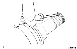
7. REMOVE FRONT AXLE SHAFT NUT
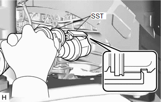
| (a) Using SST and a hammer, release the staked part of the front axle shaft nut. SST: 09930-00010 NOTICE: Fully loosen the staked part of the front axle shaft nut, otherwise the threads of the drive shaft may be damaged. |
|
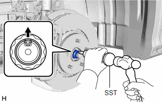
(b) While applying the brakes, remove the front axle shaft nut.
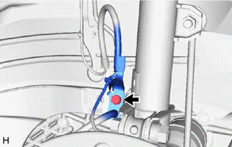
8. SEPARATE FRONT SPEED SENSOR (w/o AVS)
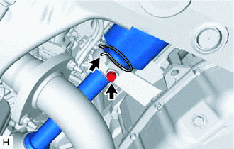
| (a) Remove the bolt and separate the front flexible hose and sensor clamp. |
|
| (b) Disengage the 2 claws to separate the sensor clamp. |
|
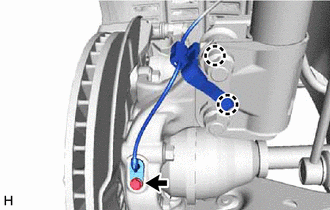
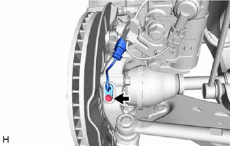
(c) Remove the bolt and separate the front speed sensor from the steering knuckle.
NOTICE:
- Keep the tip of the front speed sensor and installation hole free of foreign matter.
- Do not rotate or apply excessive force to the front speed sensor when removing it from the steering knuckle. Rotating or applying excessive force may result in damage to the front speed sensor.
9. SEPARATE FRONT SPEED SENSOR (w/ AVS)
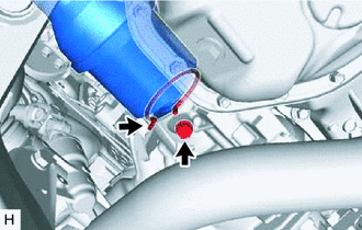
| (a) Remove the bolt and separate the front flexible hose and sensor clamp. |
|
| (b) Disconnect the connector from the front shock absorber assembly. |
|
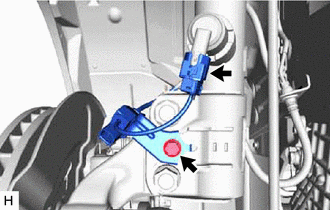
(c) Remove the bolt and separate the front skid control sensor wire from the front shock absorber assembly.
| (d) Remove the bolt and separate the front speed sensor from the steering knuckle. NOTICE:
|
|
10. SEPARATE TIE ROD ASSEMBLY
Click here
11. SEPARATE FRONT STABILIZER LINK ASSEMBLY
Click here
12. SEPARATE FRONT LOWER NO. 1 SUSPENSION ARM SUB-ASSEMBLY
Click here
13. SEPARATE FRONT DRIVE SHAFT ASSEMBLY
Click here
14. REMOVE FRONT DRIVE SHAFT ASSEMBLY LH
| (a) Using SST, remove the front drive shaft assembly LH. SST: 09520-01010 SST: 09520-24010 09520-32040 NOTICE:
|
|
15. REMOVE FRONT DRIVE SHAFT ASSEMBLY RH (for 2WD)
| (a) Separate the bearing bracket hole snap ring from the drive shaft bearing bracket. |
|
(b) Remove the No. 1 drive shaft bearing bracket setting bolt and front drive shaft assembly RH from the drive shaft bearing bracket.
NOTICE:
- Do not damage the front drive shaft oil seal RH.
- Do not damage the front axle inboard joint boot.
- Do not drop the front drive shaft assembly RH.
HINT:
If it is difficult to disengage the fitting, tap the end of the front drive inboard joint assembly with a brass bar and a hammer.
(c) Remove the bearing bracket hole snap ring from the front drive shaft assembly RH.
16. REMOVE FRONT DRIVE SHAFT ASSEMBLY RH (for AWD)
| (a) Separate the bearing bracket hole snap ring from the transfer assembly. |
|
(b) Remove the No. 1 drive shaft bearing bracket setting bolt and front drive shaft assembly RH from the transfer assembly.
NOTICE:
- Do not damage the transfer case oil seal RH.
- Do not damage the front axle inboard joint boot.
- Do not drop the front drive shaft assembly RH.
HINT:
If it is difficult to disengage the fitting, tap the end of the front drive inboard joint assembly with a brass bar and a hammer.
(c) Remove the bearing bracket hole snap ring from the front drive shaft assembly RH.
17. REMOVE FRONT DRIVE SHAFT HOLE SNAP RING (for LH Side)
| (a) Using a screwdriver, remove the front drive shaft hole snap ring. |
|
 Components
COMPONENTS ILLUSTRATION *1 FRONT FENDER APRON SEAL LH *2 FRONT WHEEL OPENING EXTENSION PAD LH *3 NO. 3 ENGINE UNDER COVER - - ILLUSTRATION *A w/o AVS *B w/ AVS *1 ...
 Inspection
INSPECTION PROCEDURE 1. INSPECT FRONT DRIVE SHAFT ASSEMBLY (a) Check that there is no excessive play in the radial direction of the outboard joint. (b) Check that the inboard joint slid ...
Other materials:
Lexus RX (RX 350L, RX450h) 2016-2026 Repair Manual > Air Conditioning System: PTC Heater Circuit
DESCRIPTION The air conditioning amplifier assembly sends operation signals to the PTC heater relays when quick heater assembly operation conditions are met. Based on the signals from the air conditioning amplifier assembly, the PTC heater relays turn on, and power is supplied to the quick heater as ...
Lexus RX (RX 350L, RX450h) 2016-2026 Repair Manual > Steering Lock System: Data List / Active Test
DATA LIST / ACTIVE TEST READ DATA LIST HINT: Using the Techstream to read the Data List allows the values or states of switches, sensors, actuators and other items to be read without removing any parts. This non-intrusive inspection can be very useful because intermittent conditions or signals may b ...
Lexus RX (RX 350L, RX450h) 2016-{YEAR} Owners Manual
- For your information
- Pictorial index
- For safety and security
- Instrument cluster
- Operation of each component
- Driving
- Lexus Display Audio system
- Interior features
- Maintenance and care
- When trouble arises
- Vehicle specifications
- For owners
Lexus RX (RX 350L, RX450h) 2016-{YEAR} Repair Manual

0.0101