Lexus RX (RX 350L, RX450h) 2016-2026 Repair Manual: Reassembly
REASSEMBLY
PROCEDURE
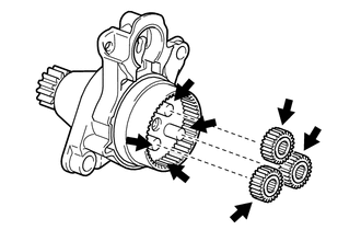
1. INSTALL PLANETARY GEAR
(a) Apply high-temperature grease to the 3 planetary gears, 3 planetary gear shafts and starter drive housing assembly.
.png) | High-temperature Grease |
(b) Install the 3 planetary gears to the starter drive housing assembly.
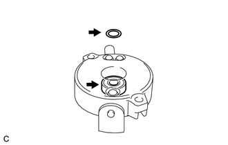
2. INSTALL RUBBER SEAL
| (a) Install the rubber seal to the starter drive housing assembly. |
|
.png)
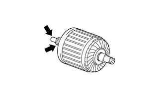
3. INSTALL STARTER ARMATURE ASSEMBLY
(a) Secure the starter commutator end frame assembly in a vise between aluminum plates.
NOTICE:
Do not overtighten the vise.
(b) Apply high-temperature grease to the starter armature shaft.
| | High-temperature Grease |
(c) Apply high-temperature grease to the washer and bearing as shown in the illustration.
| | High-temperature Grease |
(d) Install the starter armature assembly to the starter commutator end frame assembly.
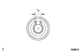
| (e) Using snap ring pliers, install the washer and a new snap ring. NOTICE:
|
|
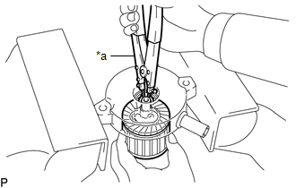
| (f) Using a vernier caliper, measure the width of the snap ring end gap as shown in the illustration. Maximum Width: 5.0 mm (0.197 in.) If the width is greater than the maximum, replace the snap ring with a new one. |
|
4. INSTALL STARTER COMMUTATOR END FRAME COVER
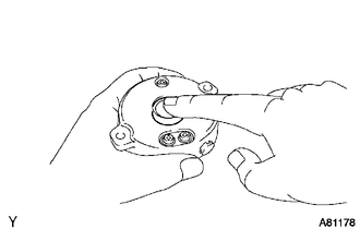
| (a) Install the starter commutator end frame cover to the starter commutator end frame assembly. |
|
5. INSTALL STARTER ARMATURE PLATE
| (a) Insert the starter armature plate to the starter yoke assembly. |
|
(b) Align the keyway of the starter armature plate with the key inside the starter yoke assembly, and install the starter armature plate.
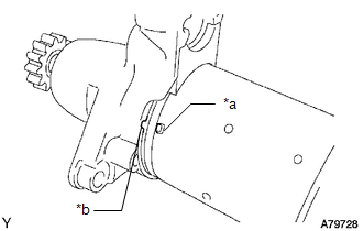
6. INSTALL STARTER COMMUTATOR END FRAME ASSEMBLY
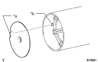
| *a | Rubber |
| *b | Cutout |
(a) Align the rubber of the starter commutator end frame assembly with the cutout of the starter yoke assembly.
(b) Install the starter commutator end frame assembly to the starter yoke assembly.
NOTICE:
The magnet of the starter yoke assembly may attract the starter armature assembly when the starter commutator end frame assembly is installed, causing the magnet to break.
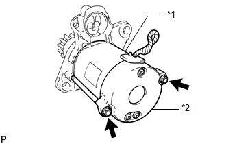
7. INSTALL STARTER YOKE ASSEMBLY
| (a) Align the protrusion of the starter yoke assembly with the cutout of the starter drive housing assembly. |
|
| (b) Install the starter yoke assembly with the 2 through bolts. Torque: 6.0 N·m {61 kgf·cm, 53 in·lbf} |
|
8. INSTALL MAGNET STARTER SWITCH ASSEMBLY
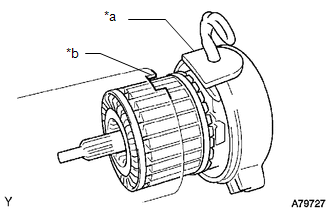
(a) Apply high-temperature grease to the magnet starter switch assembly.
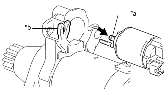
| *a | Hook |
| *b | Pinion Drive Lever |
| | High-temperature Grease |
(b) Hang the hook of the magnet starter switch assembly on the pinion drive lever.
| (c) Install the magnet starter switch assembly with the 2 nuts. Torque: 7.5 N·m {76 kgf·cm, 66 in·lbf} |
|
.png)
| (d) Connect the field coil lead wire to terminal C with the nut. Torque: 10 N·m {102 kgf·cm, 7 ft·lbf} |
|
.png)
 Installation
INSTALLATION PROCEDURE 1. INSTALL STARTER ASSEMBLY (a) Install the starter assembly with the 2 bolts. Torque: Type A : 46 N·m {469 kgf·cm, 34 ft·lbf} Type B : 37 N·m {377 kgf·cm, 27 ft·lbf ...
 Starting System
Parts LocationPARTS LOCATION ILLUSTRATION *1 STARTER ASSEMBLY *2 ECM *3 ENGINE ROOM RELAY BLOCK ASSEMBLY - ST RELAY - ST NO. 1 FUSE *4 PARK/NEUTRAL POSITION SWITCH ASSEMBLY ILLU ...
Other materials:
Lexus RX (RX 350L, RX450h) 2016-2026 Repair Manual > Transmission Control Cable: Installation
INSTALLATION PROCEDURE 1. INSTALL TRANSMISSION CONTROL CABLE ASSEMBLY NOTICE: Before installing the transmission control cable assembly, check that the park/neutral position switch assembly and the shift lever are in neutral. (a) Pass the transmission control cable assembly from the cabin to the eng ...
Lexus RX (RX 350L, RX450h) 2016-2026 Repair Manual > Power Tilt And Power Telescopic Steering Column System: System Diagram
SYSTEM DIAGRAM Communication Table Transmitting ECU (Transmitter) Receiving ECU Signal Communication Method Main Body ECU (Multiplex Network Body ECU) Multiplex Tilt and Telescopic ECU
Auto away/return state signal
Tilt and telescopic position request signal
Driver position ...
Lexus RX (RX 350L, RX450h) 2016-{YEAR} Owners Manual
- For your information
- Pictorial index
- For safety and security
- Instrument cluster
- Operation of each component
- Driving
- Lexus Display Audio system
- Interior features
- Maintenance and care
- When trouble arises
- Vehicle specifications
- For owners
Lexus RX (RX 350L, RX450h) 2016-{YEAR} Repair Manual

0.0104