Lexus RX (RX 350L, RX450h) 2016-2026 Repair Manual: Voice Recognition Microphone Disconnected (B1579)
DESCRIPTION
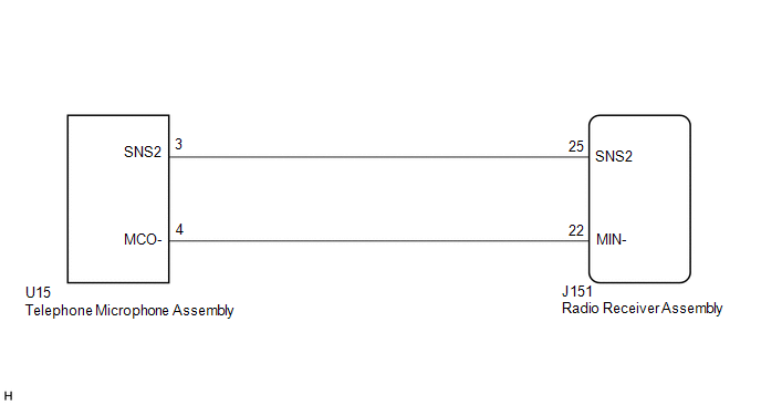
The radio receiver assembly and telephone microphone assembly are connected to each other using the microphone connection detection signal lines.
This DTC is stored when a microphone connection detection signal line is disconnected.
| DTC No. | Detection Item | DTC Detection Condition | Trouble Area |
|---|---|---|---|
| B1579 | Voice Recognition Microphone Disconnected | Microphone signal is lost. |
|
WIRING DIAGRAM
CAUTION / NOTICE / HINT
NOTICE:
Depending on the parts that are replaced during vehicle inspection or maintenance, performing initialization, registration or calibration may be needed. Refer to Precaution for Audio and Visual System.
Click here .gif)
PROCEDURE
| 1. | INSPECT RADIO RECEIVER ASSEMBLY |
| (a) Measure the resistance according to the value(s) in the table below. Standard Resistance:
|
|
| NG |  | REPLACE RADIO RECEIVER ASSEMBLY |
|

| 2. | CHECK HARNESS AND CONNECTOR (RADIO RECEIVER ASSEMBLY - TELEPHONE MICROPHONE ASSEMBLY) |
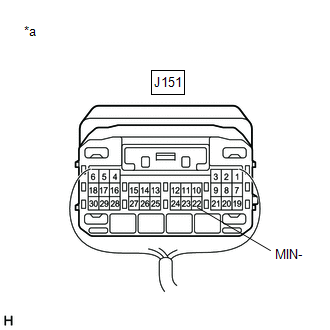
(a) Disconnect the J151 radio receiver assembly connector.
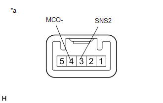
(b) Disconnect the U15 telephone microphone assembly connector.
(c) Measure the resistance according to the value(s) in the table below.
Standard Resistance:
| Tester Connection | Condition | Specified Condition |
|---|---|---|
| J151-25 (SNS2) - U15-3 (SNS2) | Always | Below 1 Ω |
| J151-22 (MIN-) - U15-4 (MCO-) | Always | Below 1 Ω |
| J151-25 (SNS2) or U15-3 (SNS2) - Body ground | Always | 10 kΩ or higher |
| J151-22 (MIN-) or U15-4 (MCO-) - Body ground | Always | 10 kΩ or higher |
| NG | | REPAIR OR REPLACE HARNESS OR CONNECTOR |
|
| 3. | INSPECT TELEPHONE MICROPHONE ASSEMBLY |
(a) Remove the telephone microphone assembly.
Click here
| (b) Measure the resistance according to the value(s) in the table below. Standard Resistance:
|
|
| OK | | REPLACE RADIO RECEIVER ASSEMBLY |
| NG | | REPLACE TELEPHONE MICROPHONE ASSEMBLY |
 GVIF Disconnected (from EMV/MM Integrated Device to Multi Display) (B1575)
DESCRIPTION The radio receiver assembly and multi-display assembly are connected via video signal (digital) lines. This DTC is stored when a video signal (digital) line is disconnected. DTC No. D ...
 USB Device Malfunction (B1585)
DESCRIPTION This DTC is stored when a malfunction occurs in a connected device. DTC No. Detection Item DTC Detection Condition Trouble Area B1585 USB Device Malfunction When any of th ...
Other materials:
Lexus RX (RX 350L, RX450h) 2016-2026 Repair Manual > Headup Display Switch: Removal
REMOVAL PROCEDURE 1. REMOVE INSTRUMENT PANEL GARNISH LH Click here 2. REMOVE FRONT DOOR SCUFF PLATE LH Click here 3. REMOVE COWL SIDE TRIM BOARD LH Click here 4. REMOVE NO. 1 INSTRUMENT PANEL UNDER COVER SUB-ASSEMBLY Click here 5. DISCONNECT HOOD LOCK CONTROL LEVER SUB-ASSEMBLY C ...
Lexus RX (RX 350L, RX450h) 2016-2026 Repair Manual > Power Mirror Control System (w/o Memory): Precaution
PRECAUTION PRECAUTION FOR DISCONNECTING CABLE FROM NEGATIVE BATTERY TERMINAL NOTICE: When disconnecting the cable from the negative (-) battery terminal, initialize the following systems after the cable is reconnected. System Name See Procedure Lane Control System Pre-collision Sys ...
Lexus RX (RX 350L, RX450h) 2016-{YEAR} Owners Manual
- For your information
- Pictorial index
- For safety and security
- Instrument cluster
- Operation of each component
- Driving
- Lexus Display Audio system
- Interior features
- Maintenance and care
- When trouble arises
- Vehicle specifications
- For owners
Lexus RX (RX 350L, RX450h) 2016-{YEAR} Repair Manual

0.0153