Lexus RX (RX 350L, RX450h) 2016-2026 Repair Manual: Pointer Displayed/not Displayed Repeatedly
WIRING DIAGRAM
CAUTION / NOTICE / HINT
NOTICE:
-
Depending on the parts that are replaced during vehicle inspection or maintenance, performing initialization, registration or calibration may be needed. Refer to Precaution for Audio and Visual System.
Click here
.gif)
- Inspect the fuses for circuits related to this system before performing the following procedure.
PROCEDURE
| 1. | CHECK SYMPTOMS |
(a) Recheck the situation when the malfunction occurs.
HINT:
- When a hand is rested on the remote touch screen while driving, the remote touch (remote operation controller assembly) may react to finger movements and repeatedly display and hide the pointer.
- When accelerating excessively on rough roads, the remote touch (remote operation controller assembly) may react to the acceleration and repeatedly display and hide the pointer.
| Result | Proceed to |
|---|---|
| Symptom occurs in any situation. | A |
| Symptom occurs when hand is rested on the remote touch screen while driving. | B |
| Symptom occurs when accelerating excessively on rough roads. | C |
| B |  | END |
| C | | GO TO STEP 5 |
|

| 2. | CHECK FOR FOREIGN MATTER |
(a) Check if there is any foreign matter around the remote touch screen that interferes with operation of the screen.
OK:
There is no foreign matter around the remote touch screen that interferes with operation of the screen.
| NG | | REMOVE FOREIGN MATTER (CHECK OPERATION AGAIN) |
|
| 3. | REMOTE TOUCH (REMOTE OPERATION CONTROLLER ASSEMBLY) SELF CHECK (CHECK REMOTE TOUCH SCREEN OPERATION POSITION RECOGNITION CONDITION) |
(a) Enter self-diagnostic mode.
Click here
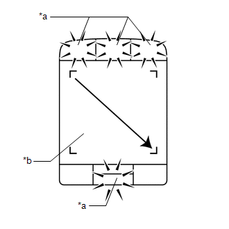
| (b) Operate the remote touch screen diagonally from the upper left to the lower right and check that the brightness of the switch illumination changes. NOTICE: Since the remote touch screen may recognize a pinch in/out operation if operated with 2 fingers, always use 1 finger to operate the remote touch screen in self-diagnostic mode. OK: Brightness changes according to touch screen operation.
HINT: When the switch illumination blinks, the remote touch (remote operation controller assembly) has stored a DTC. |
|
| B | | REPLACE REMOTE TOUCH (REMOTE OPERATION CONTROLLER ASSEMBLY) |
|
| 4. | REPLACE NAVIGATION ECU |
(a) Replace the navigation ECU with a new one.
Click here
(b) Check the malfunction disappears.
OK:
Malfunction disappears.
| OK | | END (NAVIGATION ECU IS DEFECTIVE) |
| NG | | REPLACE RADIO RECEIVER ASSEMBLY |
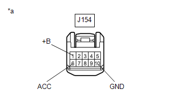
| 5. | CHECK CONNECTOR CONNECTION CONDITION |
(a) Check if the J154 remote touch (remote operation controller assembly) connector is securely connected.
OK:
The connector is securely connected.
| NG | | SECURELY CONNECTED |
|
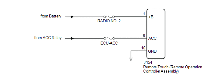
| 6. | CHECK HARNESS AND CONNECTOR (REMOTE TOUCH (REMOTE OPERATION CONTROLLER ASSEMBLY) POWER SOURCE) |
(a) Disconnect the J154 remote touch (remote operation controller assembly) connector.
| (b) Measure the resistance according to the value(s) in the table below. Standard Resistance:
|
|
(c) Measure the voltage according to the value(s) in the table below.
Standard Voltage:
| Tester Connection | Condition | Specified Condition |
|---|---|---|
| J154-1 (+B) - Body ground | Always | 11 to 14 V |
| J154-6 (ACC) - Body ground | Engine switch on (ACC) | 11 to 14 V |
| OK | | REPLACE REMOTE TOUCH (REMOTE OPERATION CONTROLLER ASSEMBLY) |
| NG | | REPAIR OR REPLACE HARNESS OR CONNECTOR |
 Switch Operation of Remote Touch not Accepted
CAUTION / NOTICE / HINT NOTICE: Depending on the parts that are replaced during vehicle inspection or maintenance, performing initialization, registration or calibration may be needed. Refer to Precau ...
 Pointer not Displayed on Screen or Pointer does not Move
CAUTION / NOTICE / HINT NOTICE: Depending on the parts that are replaced during vehicle inspection or maintenance, performing initialization, registration or calibration may be needed. Refer to Precau ...
Other materials:
Lexus RX (RX 350L, RX450h) 2016-2026 Repair Manual > 2gr-fks (starting): Starting System
Parts LocationPARTS LOCATION ILLUSTRATION *1 STARTER ASSEMBLY *2 ECM *3 ENGINE ROOM RELAY BLOCK ASSEMBLY - ST RELAY - ST NO. 1 FUSE *4 PARK/NEUTRAL POSITION SWITCH ASSEMBLY ILLUSTRATION *1 ENGINE SWITCH *2 CERTIFICATION ECU (SMART KEY ECU ASSEMBLY) System DiagramS ...
Lexus RX (RX 350L, RX450h) 2016-2026 Repair Manual > Stop Light Switch: Removal
REMOVAL CAUTION / NOTICE / HINT The necessary procedures (adjustment, calibration, initialization or registration) that must be performed after parts are removed and installed, or replaced during stop light switch removal/installation are shown below. Necessary Procedures After Parts Removed/Install ...
Lexus RX (RX 350L, RX450h) 2016-{YEAR} Owners Manual
- For your information
- Pictorial index
- For safety and security
- Instrument cluster
- Operation of each component
- Driving
- Lexus Display Audio system
- Interior features
- Maintenance and care
- When trouble arises
- Vehicle specifications
- For owners
Lexus RX (RX 350L, RX450h) 2016-{YEAR} Repair Manual

0.0134