Lexus RX (RX 350L, RX450h) 2016-2026 Repair Manual: Installation
INSTALLATION
CAUTION / NOTICE / HINT
NOTICE:
Make sure to hold the front wiper arm while lifting it as lifting the front wiper arm by the front wiper blade may damage or deform the front wiper blade.
PROCEDURE
1. INSTALL WIPER MOTOR WIRE
(a) Connect the connector to install the wiper motor wire.
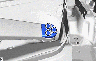
2. INSTALL FRONT WIPER MOTOR AND LINK ASSEMBLY
| (a) Temporarily install the front wiper motor and link assembly with the 5 bolts. NOTICE: Be careful not to damage the windshield glass when installing the front wiper motor and link assembly. |
|
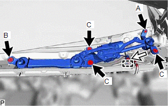
(b) Tighten the bolt (A).
Torque:
7.0 N·m {71 kgf·cm, 62 in·lbf}
(c) Tighten the bolt (B).
Torque:
7.0 N·m {71 kgf·cm, 62 in·lbf}
(d) Tighten the 3 bolts (C).
Torque:
7.0 N·m {71 kgf·cm, 62 in·lbf}
(e) Engage the clamp.
(f) Connect the connector.
3. INSTALL COWL TOP VENTILATOR LOUVER SUB-ASSEMBLY
(a) Engage the 9 guides as shown in the illustration.
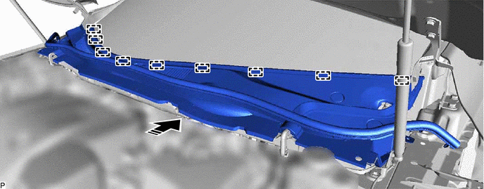
.png) | Install in this Direction | - | - |
(b) Engage the 3 guides and 6 claws to install the cowl top ventilator louver sub-assembly as shown in the illustration.

(c) Engage the 2 clips to connect the windshield outside moulding LH and windshield outside moulding RH.
(d) Install the 2 clips.
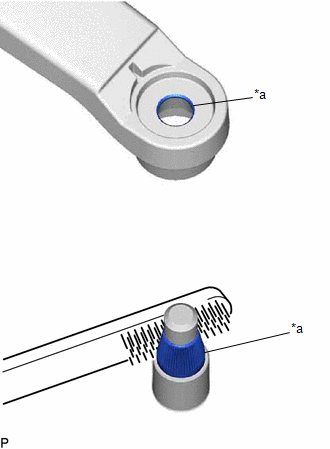
4. INSTALL FRONT WIPER ARM AND BLADE ASSEMBLY RH
(a) When reusing the front wiper arm and blade assembly RH:
| (1) Clean the 2 wiper arm serrations to remove any burrs, dirt, etc. NOTICE: Do not grind down the wiper arm serrations. |
|
(b) When reusing the front wiper motor and link assembly:
(1) Clean the 2 wiper pivot serrations with a wire brush.
(c) Turn the engine switch on (IG).
(d) Operate the wiper and stop the front wiper motor and link assembly at the automatic stop position.
(e) Turn the engine switch off.
| (f) While holding the front wiper arm and blade assembly RH at the position shown in the illustration, install the front wiper arm and blade assembly RH with the 2 nuts. Torque: 24 N·m {245 kgf·cm, 18 ft·lbf} NOTICE: As the front wiper arm and blade assembly RH and the surrounding components may be damaged, make sure to hold the front wiper arm and blade assembly RH when installing the 2 nuts. Reference Measurement:
|
|
.png)
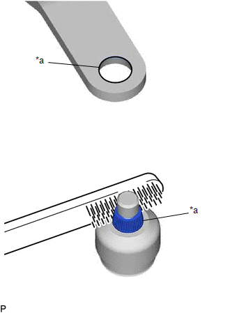
5. INSTALL FRONT WIPER ARM AND BLADE ASSEMBLY LH
(a) When reusing the front wiper arm and blade assembly LH:
| (1) Clean the wiper arm serrations to remove any burrs, dirt, etc. NOTICE: Do not grind down the wiper arm serrations. |
|
(b) When reusing the front wiper motor and link assembly:
(1) Clean the wiper pivot serrations with a wire brush.
| (c) Install the front wiper arm and blade assembly LH with the nut to the position shown in the illustration. Torque: 24 N·m {245 kgf·cm, 18 ft·lbf} HINT: Hold the wiper arm by hand while tightening the nut. Reference Measurement:
|
|
.png)
(d) Turn the engine switch on (IG).
(e) Operate the windshield wipers while spraying washer fluid onto the windshield glass. Make sure that the windshield wipers function properly and the wipers do not come into contact with the vehicle body.
(f) Turn the engine switch off.
(g) Lift each wiper arm twice after the wipers stop and check the wiper set position.
6. INSTALL FRONT WIPER ARM HEAD CAP
| (a) Engage the 3 claws to install the front wiper arm head cap. |
|
7. INSTALL FRONT FENDER REINFORCEMENT SUB-ASSEMBLY TOP LH
(a) Engage the 4 guides and 3 claws to install the front fender reinforcement sub-assembly top LH.
(b) Engage the 2 clips to connect the cowl top ventilator louver sub-assembly.
(c) Install the center hood cushion and 2 clips.
8. INSTALL FRONT FENDER REINFORCEMENT SUB-ASSEMBLY TOP RH
HINT:
Use the same procedure as for the LH side.
9. INSTALL COOL AIR INTAKE DUCT SEAL
Click here .gif)
 Inspection
INSPECTION CAUTION / NOTICE / HINT CAUTION: Ensure that fingers or articles of clothing do not get caught in moving parts when performing this test. PROCEDURE 1. INSPECT FRONT WIPER MOTOR AND LINK ASS ...
 Front Wiper Rubber
ComponentsCOMPONENTS ILLUSTRATION *1 FRONT WIPER BLADE *2 FRONT WIPER BLADE RUBBER ReplacementREPLACEMENT CAUTION / NOTICE / HINT NOTICE: Make sure to hold the front wiper arm while lifti ...
Other materials:
Lexus RX (RX 350L, RX450h) 2016-2026 Repair Manual > Sfi System: Starter Signal Circuit
DESCRIPTION While the engine is being cranked, current flows from terminal STAR of the certification ECU (smart key ECU assembly) to the park/neutral position switch assembly and to terminal STA of the ECM (STA signal). WIRING DIAGRAM CAUTION / NOTICE / HINT NOTICE: Inspect the fuses for circuits r ...
Lexus RX (RX 350L, RX450h) 2016-2026 Repair Manual > Meter / Gauge System: Meter Illumination does not Dim at Night
DESCRIPTION In this circuit, the combination meter assembly receives auto dimmer signals from the main body ECU (multiplex network body ECU) via CAN communication. When the combination meter assembly receives an auto dimmer signal, it dims the meter illumination (warning and indicator lights). The m ...
Lexus RX (RX 350L, RX450h) 2016-{YEAR} Owners Manual
- For your information
- Pictorial index
- For safety and security
- Instrument cluster
- Operation of each component
- Driving
- Lexus Display Audio system
- Interior features
- Maintenance and care
- When trouble arises
- Vehicle specifications
- For owners
Lexus RX (RX 350L, RX450h) 2016-{YEAR} Repair Manual

0.0093