Lexus RX (RX 350L, RX450h) 2016-2026 Repair Manual: Operation Check
OPERATION CHECK
HINT:
The blind spot monitor beam axis confirmation is performed to confirm whether the sensor's beam axis is correct, and perform adjustment of the beam axis by using reflector.
BLIND SPOT MONITOR BEAM AXIS CONFIRMATION
(a) When performing the blind spot monitor beam axis confirmation, move the vehicle to a place where the space shown in the illustration can be secured.

NOTICE:
- Perform this inspection on level ground.
- Make sure that there are no metal objects around the vehicle or on the ground.
- Unload the vehicle before beginning the inspection.
- Confirm that the tire pressure is correct before beginning the inspection.
- Do not place any objects other than the reflector (such as a large metallic object) in or allow people to enter the inspection area (W 6 m (19.68 ft.) x L 6 m (19.68 ft.) x H 4 m (13.12 ft.)) shown in the illustration.
(b) Place the reflector.
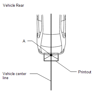
(1) From the center of the rear bumper (center of the emblem), hang a weight with a pointed tip, and mark the rear center point of the vehicle on the ground (mark A).
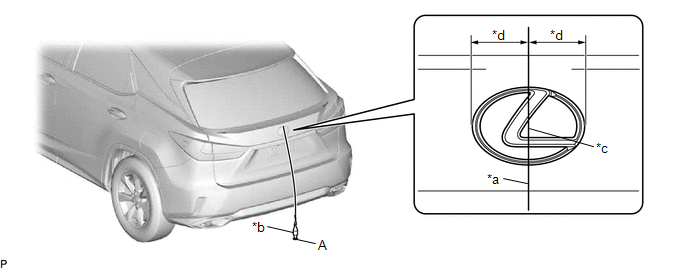
| *a | String | *b | Weight |
| *c | Center point | *d | Equal Distance to Center |
HINT:
Lightly flick the string with your fingers several times to confirm that the string is aligned with mark A.
(2) From the center of the front bumper (center of the emblem), hang a weight with a pointed tip, and mark the front center point of the vehicle on the ground (mark B).
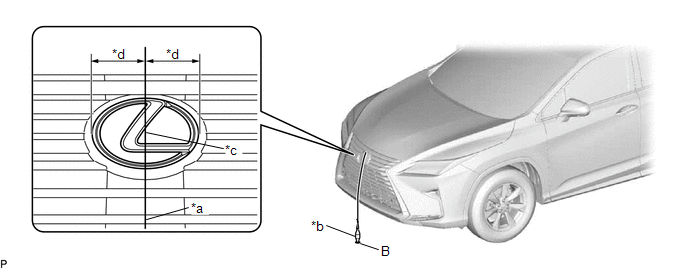
| *a | String | *b | Weight |
| *c | Center point | *d | Equal Distance to Center |
HINT:
Lightly flick the string with your fingers several times to confirm that the string is aligned with mark (B).
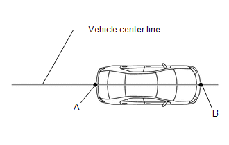
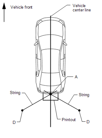
(3) Draw a vehicle center line so that it passes through mark A and B (front and rear center points).
(4) Print out the following illustration on a large piece of paper.
w/o Rear No.2 Seat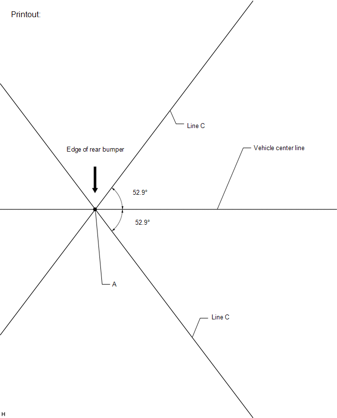 w/ Rear No.2 Seat
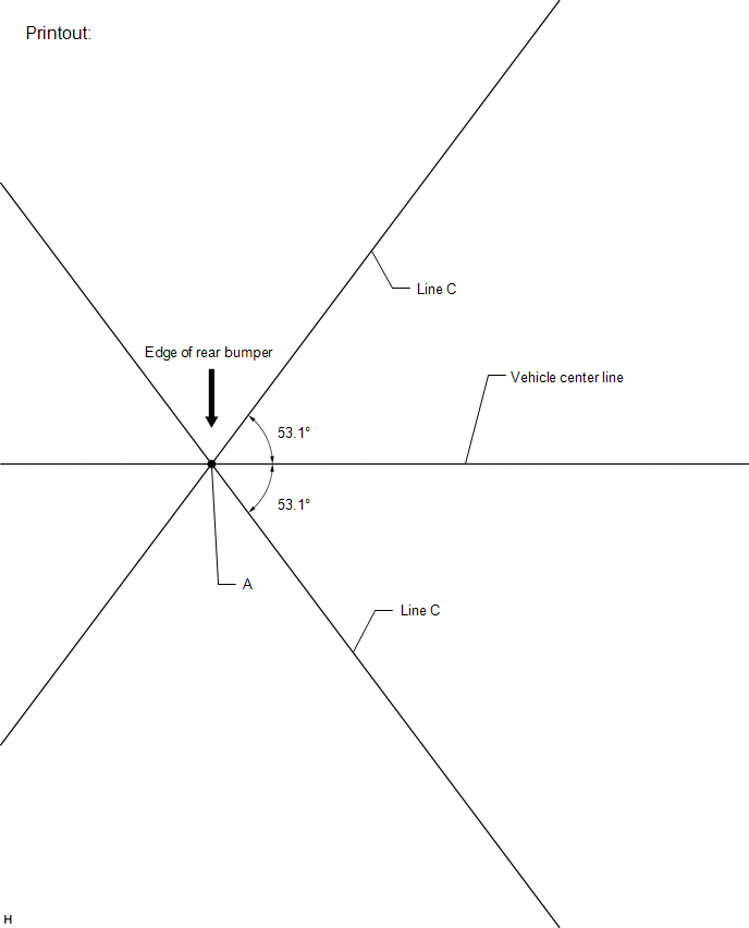
(5) Place the printout on the floor with the point A aligned with the longitudinal center line of the vehicle.
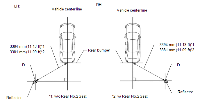
(6) Align a piece of string with line C and mark point D at a distance of 3394 mm (11.13 ft.)*1 or 3381 mm (11.09 ft.)*2 from point A.
- *1: w/o Rear No.2 Seat
- *2: w/ Rear No.2 Seat
(7) Set the reflector at the point D shown in the illustration below.
SST: 09870-60000
09870-60010
SST: 09870-60040
NOTICE:
-
Set the reflector so that its center is 865 mm (2.84 ft.)*1 or 867 mm (2.84 ft.) above the ground.
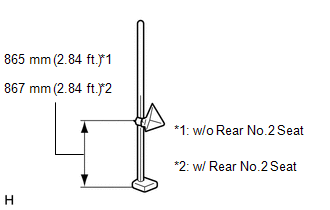
-
The center of the triangular pyramid is the reference point for the setting position and angle.
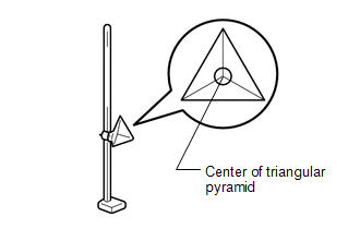
- Set the reflector as shown in the illustration so that the center of the triangular pyramid faces the blind spot monitor sensor.
- *1: w/o Rear No.2 Seat
- *2: w/ Rear No.2 Seat
(c) Perform the blind spot monitor beam axis display.
(1) Connect the Techstream to the DLC3.
(2) Turn the engine switch on (IG).
(3) Turn the blind spot monitor system on.
(4) Turn the Techstream on.
(5) Enter the following menus: Body Electrical / Blind Spot Monitor Master or Blind Spot Monitor Slave / Utility / BSM Master Beam Axis Display or BSM Slave Beam Axis Display.
Body Electrical > Blind Spot Monitor Master > Utility| Tester Display |
|---|
| BSM Master Beam Axis Display |
| Tester Display |
|---|
| BSM Slave Beam Axis Display |
(6) Check the results displayed for the BSM beam axis display.
Allowable Range:
| Item | Blind Spot Monitor Sensor LH | Blind Spot Monitor Sensor RH |
|---|---|---|
| Angle | -1.11 to +1.11° | -1.11 to +1.11° |
HINT:
If the results are outside the allowable range, try again as the reflector setting position may be incorrect or a metal object may exist near the detection area.
(d) Perform the blind spot monitor beam axis adjustment.
(1) Enter the following menus: Body Electrical / Blind Spot Monitor Master or Blind Spot Monitor Slave / Utility / BSM Master Beam Axis Adjustment or BSM Slave Beam Axis Adjustment.
HINT:
When values on the axis display are in the allowable range, performing this adjustment compensates for any deviation from the normal value.
Body Electrical > Blind Spot Monitor Master > Utility| Tester Display |
|---|
| BSM Master Beam Axis Adjustment |
| Tester Display |
|---|
| BSM Slave Beam Axis Adjustment |
BLIND SPOT MONITOR SENSOR INSTALLATION CONDITION INSPECTION
NOTICE:
- Perform this inspection on level ground.
- Unload the vehicle before beginning the inspection.
- Confirm that the tire pressure is correct before beginning the inspection.
HINT:
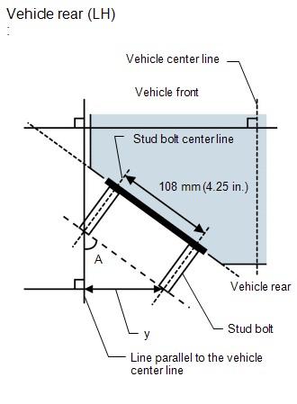
The blind spot monitor sensor installation condition inspection is performed to confirm whether the sensor is perpendicular to the floor surface (+/-4°) by using a jig, and that the sensor is 46 to 54° from the line parallel to the vehicle center line.
(a) Remove the rear bumper.
REAR BUMPER (w/o Rear No. 2 Seat): Click here .gif)
REAR BUMPER (w/ Rear No. 2 Seat): Click here
(b) Attach a jig similar to the one shown in the illustration to the outward facing surface of the blind spot monitor sensor and check that the measurement or angle is within the allowable range to confirm that the blind spot monitor sensor is perpendicular to the floor surface (+/-4°).
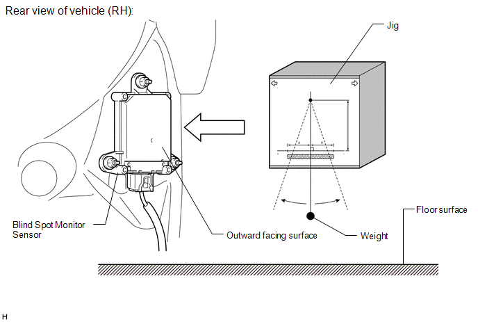
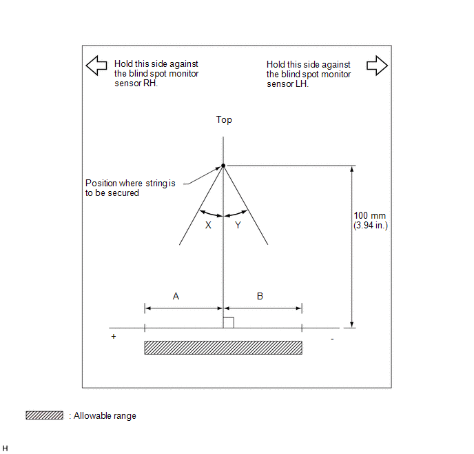 Standard
 | Item | A | B |
|---|---|---|
| Blind spot monitor sensor LH | 7 mm (0.276 in.) | -7 mm (-0.276 in.) |
| Blind spot monitor sensor RH | 7 mm (0.276 in.) | -7 mm (-0.276 in.) |
| Item | X | Y |
|---|---|---|
| Blind spot monitor sensor LH | 4° | -4° |
| Blind spot monitor sensor RH | 4° | -4° |
(c) Using the sensor installation stud bolt center lines as a reference, check that the stud bolts are as shown in the illustration.
Standard:
| Dimension | Specified Value |
|---|---|
| y | 78 to 87 mm (3.07 to 3.43 in.) |
| Degree | Specified Value |
|---|---|
| A | 46 to 54° |
 Customize Parameters
CUSTOMIZE PARAMETERS CUSTOMIZE BLIND SPOT MONITOR SYSTEM (a) Customizing with the Techstream NOTICE:
When the customer requests a change in a function, first make sure that the function can be cust ...
 Problem Symptoms Table
PROBLEM SYMPTOMS TABLE HINT:
Use the table below to help determine the cause of problem symptoms. If multiple suspected areas are listed, the potential causes of the symptoms are listed in order of ...
Other materials:
Lexus RX (RX 350L, RX450h) 2016-2026 Repair Manual > Steering Column Assembly: Installation
INSTALLATION PROCEDURE 1. ALIGN FRONT WHEELS FACING STRAIGHT AHEAD 2. INSTALL STEERING COLUMN ASSEMBLY NOTICE: Make sure that the wire harness is not interfering with the steering column assembly. (a) Install the steering column assembly with the bolt and 2 nuts. Torque: 36 N·m {367 kgf·cm, 27 ft ...
Lexus RX (RX 350L, RX450h) 2016-2026 Repair Manual > Blind Spot Monitor System: Open in Outer Mirror Indicator(Master) (C1AB4)
DESCRIPTION This DTC is stored when the blind spot monitor sensor LH detects an open in the outer rear view mirror indicator LH. DTC No. Detection Item DTC Detection Condition Trouble Area C1AB4 Open in Outer Mirror Indicator(Master) Both of the following conditions are met:
The ...
Lexus RX (RX 350L, RX450h) 2016-{YEAR} Owners Manual
- For your information
- Pictorial index
- For safety and security
- Instrument cluster
- Operation of each component
- Driving
- Lexus Display Audio system
- Interior features
- Maintenance and care
- When trouble arises
- Vehicle specifications
- For owners
Lexus RX (RX 350L, RX450h) 2016-{YEAR} Repair Manual

0.0086