Lexus RX (RX 350L, RX450h) 2016-2026 Repair Manual: Removal
REMOVAL
CAUTION / NOTICE / HINT
HINT:
- Use the same procedure for the RH side and LH side.
- The following procedure is for the LH side.
PROCEDURE
1. REMOVE FRONT WHEEL
Click here 
2. DRAIN BRAKE FLUID
NOTICE:
If brake fluid leaks onto any painted surface, immediately wash it off.
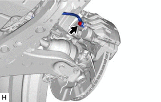
3. DISCONNECT FRONT FLEXIBLE HOSE
| (a) Remove the union bolt and gasket, and disconnect the front flexible hose from the front disc brake cylinder assembly. |
|
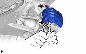
4. REMOVE FRONT DISC BRAKE CYLINDER ASSEMBLY
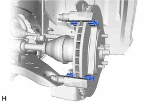
| (a) Hold the 2 front disc brake cylinder slide pins and remove the 2 bolts and front disc brake cylinder assembly. |
|
5. REMOVE FRONT DISC BRAKE PAD
| (a) Remove the 2 anti-squeal springs. |
|
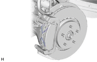
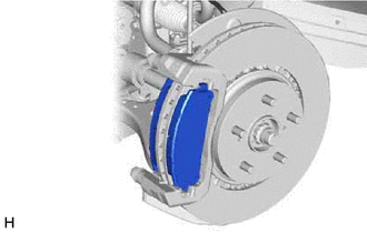
| (b) Remove the 2 front disc brake pads from the front disc brake cylinder mounting. |
|
6. REMOVE FRONT DISC BRAKE ANTI-SQUEAL SHIM KIT
(a) Remove the front disc brake anti-squeal shim from each front disc brake pad.
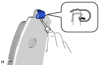
| (b) Using a screwdriver, remove the front disc brake pad wear indicator plate from each front disc brake pad. |
|
7. REMOVE FRONT DISC BRAKE PAD SUPPORT PLATE
| (a) Remove the 4 front disc brake pad support plates from the front disc brake cylinder mounting. NOTICE: Each front disc brake pad support plate has a different shape. Be sure to put an identification mark on each front disc brake pad support plate so that it can be reinstalled to its original position. |
|
8. REMOVE FRONT DISC BRAKE CYLINDER SLIDE PIN
| (a) Remove the 2 front disc brake cylinder slide pins from the front disc brake cylinder mounting. |
|
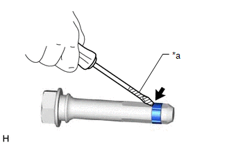
| (b) Using a screwdriver with its tip wrapped with protective tape, remove the front disc brake cylinder slide bushing from the front disc brake cylinder slide pin (lower side). NOTICE: Do not damage the front disc brake cylinder slide pin. |
|
9. REMOVE FRONT DISC BRAKE BUSHING DUST BOOT
| (a) Remove the 2 front disc brake bushing dust boots from the front disc brake cylinder mounting. |
|

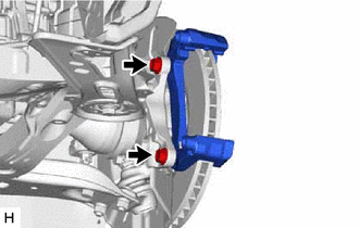
10. REMOVE FRONT DISC BRAKE CYLINDER MOUNTING
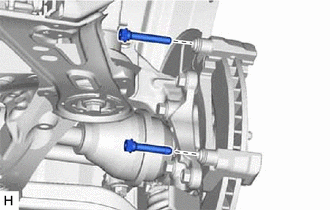
| (a) Remove the 2 bolts and front disc brake cylinder mounting from the steering knuckle. |
|
11. REMOVE FRONT DISC
| (a) Put matchmarks on the front disc and the front axle hub sub-assembly. |
|
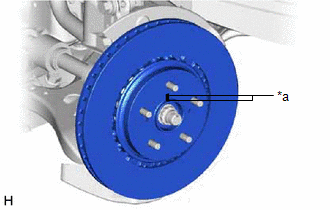
(b) Remove the front disc.
 Components
COMPONENTS ILLUSTRATION *1 FRONT DISC BRAKE CYLINDER ASSEMBLY *2 FRONT FLEXIBLE HOSE *3 FRONT DISC BRAKE PAD *4 FRONT DISC BRAKE ANTI-SQUEAL SHIM *5 FRONT DISC BRAKE PAD WEAR ...
 Disassembly
DISASSEMBLY CAUTION / NOTICE / HINT HINT: Perform the removal and installation of the front disc brake piston, cylinder boot and piston seal one side at a time. PROCEDURE 1. REMOVE FRONT DISC BRAKE PI ...
Other materials:
Lexus RX (RX 350L, RX450h) 2016-2026 Repair Manual > Headup Display System: Parts Location
PARTS LOCATION ILLUSTRATION *1 HEADUP DISPLAY SWITCH ASSEMBLY *2 INTEGRATION CONTROL AND PANEL ASSEMBLY *3 RADIO RECEIVER ASSEMBLY *4 COMBINATION METER ASSEMBLY *5 HEADUP DISPLAY (METER MIRROR SUB-ASSEMBLY) *6 INSTRUMENT PANEL JUNCTION BLOCK ASSEMBLY - ECU-DCC NO. 2 FUS ...
Lexus RX (RX 350L, RX450h) 2016-2026 Owners Manual > Lexus Display
Audio system: Setup
Setup menu
The Lexus Display Audio system can be adjusted to the desired settings.
Display "Setup" screen
Go to "Setup": "MENU" button →"Setup"
Change the settings for operation
sounds, screen animation, etc.
Change the settings for voice guidance.
Change the settings for registering, ...
Lexus RX (RX 350L, RX450h) 2016-{YEAR} Owners Manual
- For your information
- Pictorial index
- For safety and security
- Instrument cluster
- Operation of each component
- Driving
- Lexus Display Audio system
- Interior features
- Maintenance and care
- When trouble arises
- Vehicle specifications
- For owners
Lexus RX (RX 350L, RX450h) 2016-{YEAR} Repair Manual

0.0121